Replace the display module – Rockwell Automation 2711P-xxxx PanelView Plus 6 Terminals User Manual User Manual
Page 123
Rockwell Automation Publication 2711P-UM006C-EN-P - April 2013
123
Install and Replace Components
Chapter 5
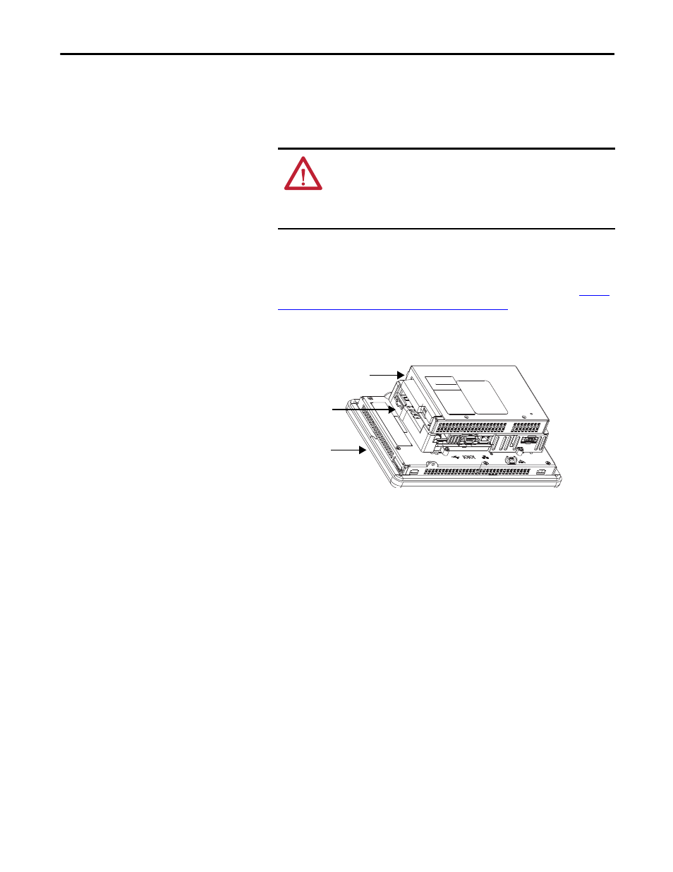
Follow these steps to replace a communication module.
1. Disconnect power from the terminal.
2. Disconnect communication cables from the module.
3. Remove the four screws that secure the communication module.
4. Carefully lift the communication module away from the logic module.
5. Install the new communication module by following steps 4…6 in
or Replace a Communication Module on page 121
Replace the Display Module
Follow these steps to replace a 700, 1000, 1250, or 1500 display module.
Follow these steps to replace the display module.
1. Disconnect power from the terminal.
2. Remove the terminal from the panel.
3. Detach the communication module, if attached, from the logic module by
removing the four screws.
4. Loosen the four captive screws that attach the logic module to the display
module.
5. Carefully lift the logic module from the display module.
6. Set the display module aside.
WARNING: Do not connect or disconnect any communication cable
with power applied to this device or any device on a network. An
electrical arc could cause an explosion in hazardous location
installations. Be sure power is removed or the area is known to be
nonhazardous before proceeding.
Communication Module
Display Module
Logic Module