Message format, Error codes – Rockwell Automation 1785-Vx0B, D17856.5.9 PLC-5 VME VMEbus Programmable Controllers User Manual User Manual
Page 78
Chapter 6
PLC-5/VME Processor
Communications Commands
6-9
See the “Header Bit/Byte Descriptions” section on page 6-4 for
descriptions of all bytes except the following:
Use the:
To specify:
PLC-5/VME processor
ADDR field
the address of the element(s) to be modified. You can use the 242-byte
address/mask field to modify selected words in and between data files.
AND mask (2-bytes
field)
which bits are reset to 0 in the addressed word. A 0 in the AND mask
resets the corresponding bit in the addressed word to 0. A 1 in the AND
mask leaves the corresponds bit unchanged. Low byte comes first in the
AND mask.
OR mask
(2-byte field)
which bits to set to 1 in the addressed word. A 1 in the OR mask sets to 1
the corresponding bit the addressed word. A 0 in the OR mask leaves the
corresponding bit unchanged. Low byte comes first in the OR mask.
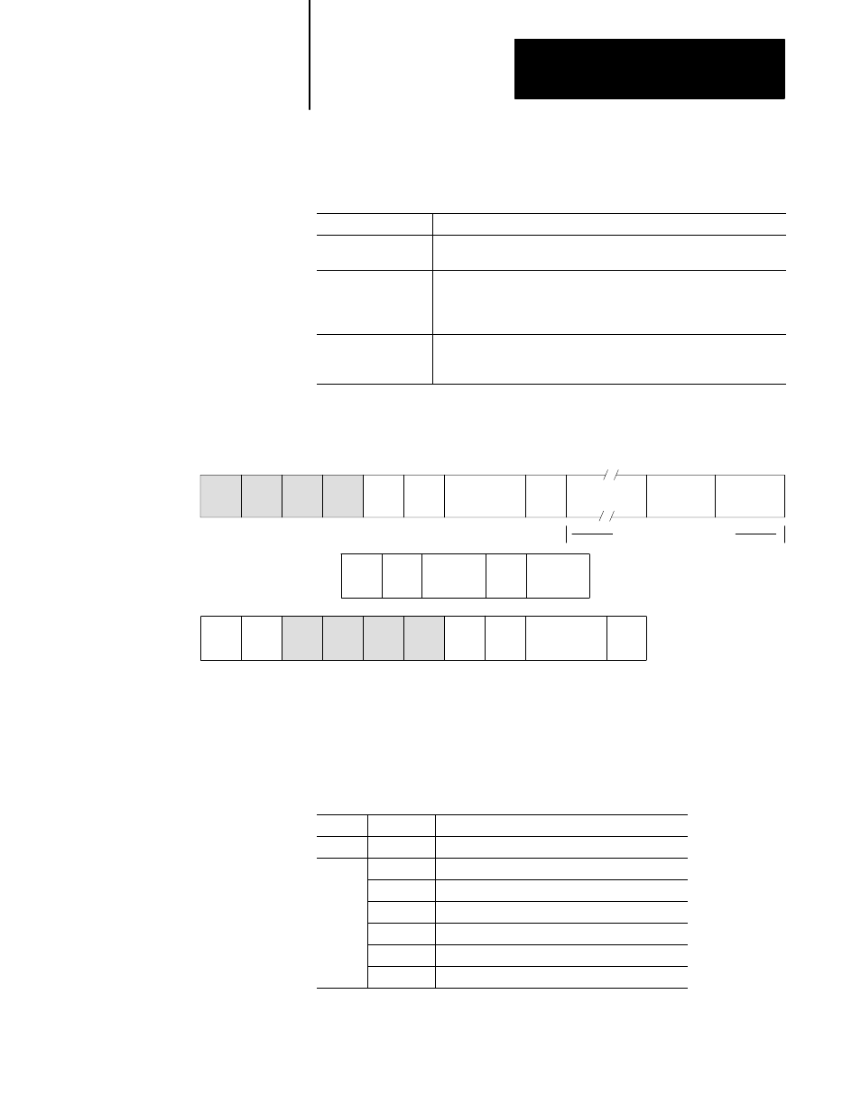
Message Format
PLC-V5
DST
00
PSN
00
SRC
00
PSN
00
CMD
0F
STS
00
TNS
FNC
26H
Command Packet
LNH
Hi
LNH
Lo
DST
00
PSN
00
SRC
00
PSN
00
CMD
4FH
STS
Reply Packet
TNS
repeats, up to 242 bytes
AND
Lo
Hi
OR
Lo
Hi
EXT
STS
06
FF
FILE #
Lo
FF
ELEM #
Lo
PLC-V5 ADDR
Hi
Hi
ADDRESS
Error Codes
Extended status codes are reported in the response packet. The STS byte
contains 00H if no error, F0H when the PLC-5/VME processor detects an
error. If an error, the error code is indicated in the EXT STS byte
as follows:
STS
EXT STS
Description
00H
–
No error
F0H
01H
Illegal address—address field has an illegal value
02H
Illegal address—not enough fields specified
03H
Illegal address—specified too many address levels
06H
Illegal address—file does not exist
07H
Beyond end of file
0BH
Access denied—privilege violation
Refer to page D-3 for additional information on PCCC status codes.