6 - plc-5/vme processor communications commands, Chapter objectives, Pccc structure – Rockwell Automation 1785-Vx0B, D17856.5.9 PLC-5 VME VMEbus Programmable Controllers User Manual User Manual
Page 70: Plc-5/vme processor communications commands, Chapter objectives pccc structure
6
Chapter
6-1
PLC-5/VME Processor Communications
Commands
Read this chapter to understand the function of the extended PCCCs in the
PLC-5/VME processor.
Important: Numerical data in the extended PCCCs is defined in
little-endian (Intel) format.
See the Data Highway / Data Highway Plus / DH-485 Communication
Protocol and Command Set reference manual, publication number
1770-6.5.16, for more information on PCCC commands.
PCCCs are transferred in a command packet attached to a send-PCCC
command. When the PLC-5/VME processor has finished processing the
PCCC, a reply is returned by appending a reply packet to the PCCC
command packet.
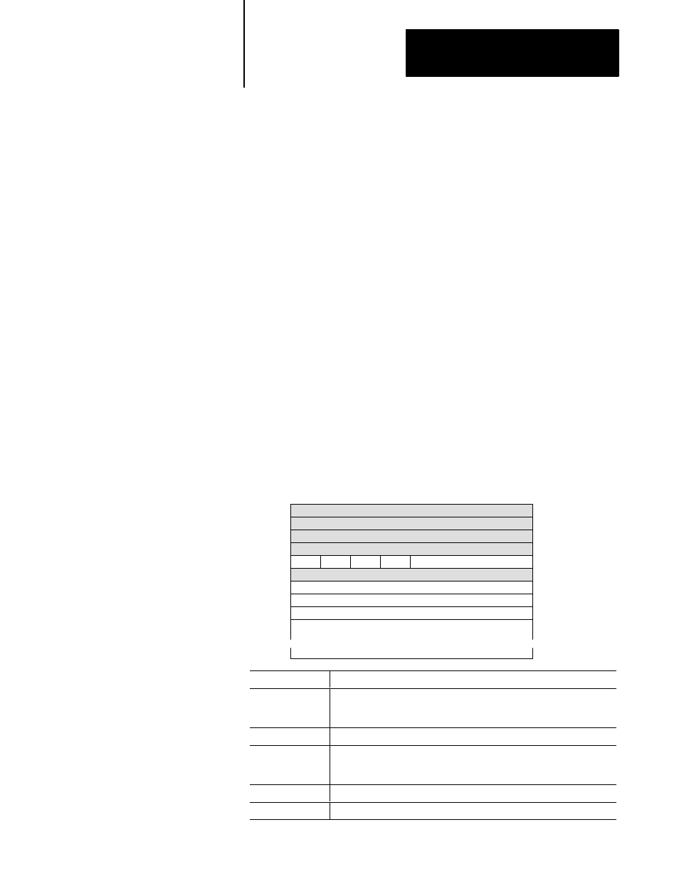
A PCCC command packet has the following format:
7
6
5
4
3
2
1
0
Byte
0
1
2
3
4
5
6
7
8
9
0
0
0
0
COMMAND
TNS – first byte
TNS – second byte
FUNCTION CODE (FNC)
OPTIONAL DATA
(up to 243 bytes)
Reserved
Reserved
Reserved
Reserved
Reserved
Bit
(DST)
(PSN)
(SRC)
(PSN)
Command
Description
First four words
Currently unused and unexamined. To assure compatibility with any future
use of these bytes, they should be initialized to 0. DST, PSN and SRC are
included for reference only.
COMMAND
Specifies the PCCC command type.
TNS
Transaction or sequence word. A value that is copied into the reply packet
to associate commands with replies. There cannot be more than one PCCC
active in the PLC-5/VME processor with the same TNS from any source.
FUNCTION CODE
This is an extension of the COMMAND field.
OPTIONAL DATA
The value(s) and size of this field are specific to the type of command.
Chapter Objectives
PCCC Structure