Configuring the vme backplane jumpers – Rockwell Automation 1785-Vx0B, D17856.5.9 PLC-5 VME VMEbus Programmable Controllers User Manual User Manual
Page 26
Chapter 2
Installation
2-4
Table 2.D
Address Range SW2 (Switches 1-3)
ULA
1
1
2
3
A16 Address Range
0
on
on
on
FC00-FC3F (hex)
1
off
on
on
FC40-FC7F
2
on
off
on
FC80-FCBF
3
off
off
on
FCC0-FCFF
4
on
on
off
FD00-FD3F
5
off
on
off
FD40-FD7F
6
on
off
off
FD80-FDBF
7
off
off
off
FDC0-FDFF
1
Unique Logical Address is used by the 6200 series
programming software to determine the A16 base address of
the PLC-5/VME processor’s registers..
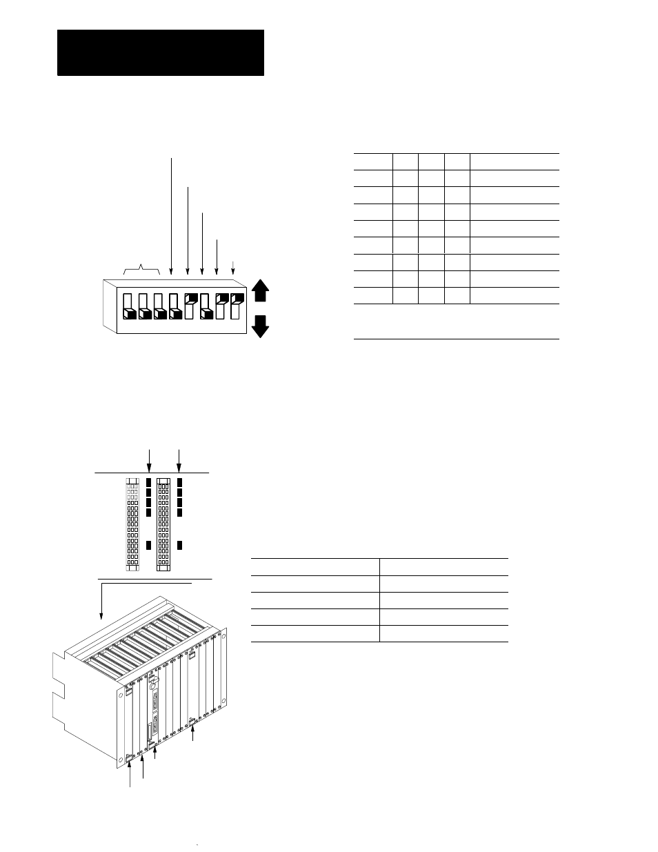
The VMEbus contains several daisy-chained control signals. Almost all
VMEbus backplanes contain jumpers for these control signals to allow
systems to operate with empty slots. Failing to install these jumpers
properly is a common source of problems in configuring a new
VMEbus system.
There are five jumpers per VME slot, one for each of the four bus-grant
arbitration levels and one for the interrupt-acknowledge daisy chain.
Depending on the backplane manufacturer, the jumpers can be on the
rear pins of the J1 connector or alongside it on the front of the backplane.
The PLC-5/VME processor uses two slots. Based on what is in the VME
slot, install or remove the backplane jumpers as follows:
VME Slot Content
Five Backplane Jumpers
PLC-5/VME processor’s left slot
Remove
PLC-5/VME processor’s right slot
Install
Empty slot
Install
Other VME module
Consult manufacturer’s literature
A16
address
range
Unused
(off)
System
controller
Request
level
Unused
(off)
Unused
(off)
SW2 set of switches
Up
(off)
Down
(on)
1
2
3
4
5
6
7
8
Configuring the VME
Backplane Jumpers
Five backplane jumpers
Right
connector
Left
connector
Backplane
CPU
Empty
PLC-5/VME processor
Other VME module
Note: Consult
manufacturer’s
literature.