Connecting a dh+ link – Rockwell Automation 1785-Vx0B, D17856.5.9 PLC-5 VME VMEbus Programmable Controllers User Manual User Manual
Page 34
Chapter 2
Installation
2-12
Once you connect the programming device through a local DH+ link to
one processor, the device can communicate with any PLC-5/VME
processor on the link. You can also communicate with PLC-2, PLC-3, and
PLC-5/250 processors connected to the link provided you have the
appropriate programming software installed.
The processor has electrically parallel DH+ connectors.
This processor:
Has these electrically parallel DH+ connectors:
PLC-5/V40B
PLC-5/V80B
•
8-pin connector for each of channel 1A and 2A
•
3-pin connector on each of channel 1A and 2A
Channels 1A and 2A must be configured to support DH+ communication
to use the connectors described above. Note that Channel 1A’s default
configuration is DH+ communication.
Channels 1B and 2B can also support DH+ communication if properly
configured, but they do not have parallel connectors.
PLC-5/V40L
•
8-pin connector for channel 1A
•
3-pin connector for channel 1A
Channel 1A must be configured to support DH+ communication to use the
connectors described above. Note that Channel 1A’s default configuration
is DH+ communication.
Channel 1B can also support DH+ communication if properly configured,
but it does not have parallel connectors.
Use the Belden 9463 twinaxial cable (1770-CD) to connect the processor
to the DH+ link.
Follow these guidelines while installing DH+ communication links:
do not exceed these cable lengths:
- trunkline-cable length—3,048 m (10,000 cable-ft)
- drop-cable length—30.4 m (100 cable-ft)
do not connect more than 64 stations on a single DH+ link
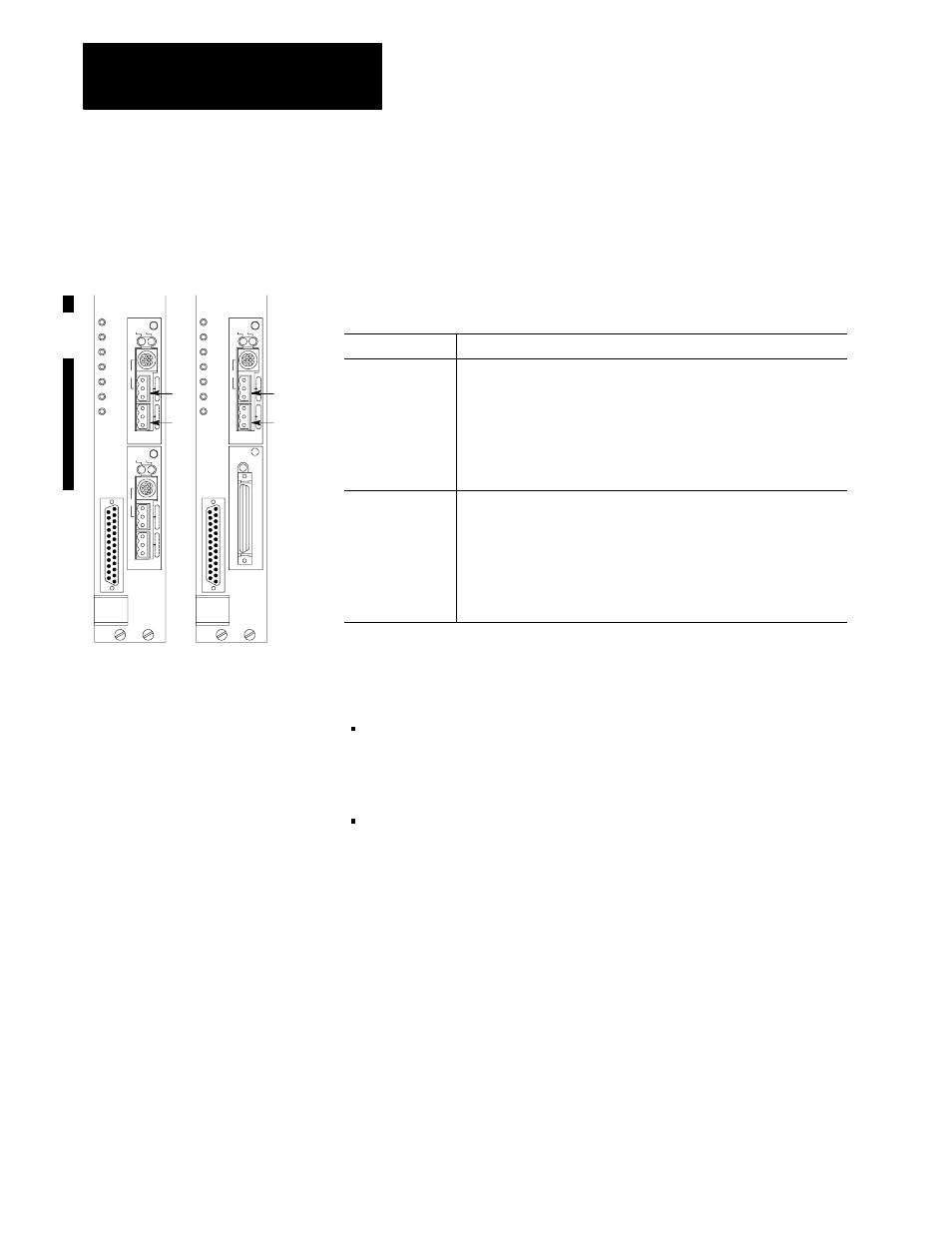
Connecting a DH+ Link
Chan 0
Chan 2
Chan 1
Chan 0
Chan 2
Chan 1
PLC-5/V40B
PLC-5/V40L
1A
1B
1A
1B
or -5/V80B