Handling the processor, Setting the switches – Rockwell Automation 1785-Vx0B, D17856.5.9 PLC-5 VME VMEbus Programmable Controllers User Manual User Manual
Page 24
Chapter 2
Installation
2-2
The processor is shipped in a static-shielded container to guard against
electrostatic damage. Electrostatic discharge can damage integrated
circuits or semiconductors in the processor module if you touch backplane
connector pins. It can also damage the module when you set configuration
plugs or switches inside the module. Avoid electrostatic damage by
observing the following precautions.
Remain in contact with an approved ground point while handling the
module (by wearing a properly grounded wrist strap).
Do not touch the backplane connector or connector pins.
When not in use, keep the module in its static-shielded container.
Before installing the PLC-5/VME processor, you need to make some
decisions about its configuration and operation and set the switches on the
circuit board accordingly. You need to know:
DH+ station (node) number
Memory protection—whether you want the processor’s program
RAM protected
Location of configuration registers in VMEbus A16 address space
System controller—whether you want the processor to serve as the
VMEbus slot-1 system controller
VMEbus request level—whether you want the processor to request
access to the VMEbus at level 3 or level 1
Figure 2.1
Switch Location
SW1
SW2
19502
Front plate
Bottom
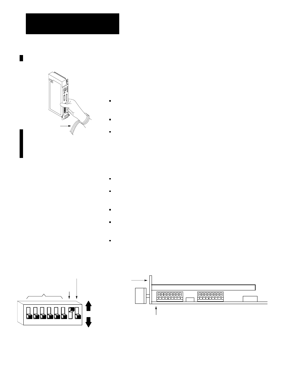
Table 2.A and Table 2.B describe the switch settings for SW1.
Handling the Processor
Wrist strap
19897
DH+ station
number
Power-
up Test
Memory
protect
SW1 set of switches
Up
(off)
Down
(on)
1
2
3
4
5
6
7
8
Setting the Switches