Notes on copy operations – Rockwell Automation 1785-Vx0B, D17856.5.9 PLC-5 VME VMEbus Programmable Controllers User Manual User Manual
Page 64
Chapter 5
Commands
5-3
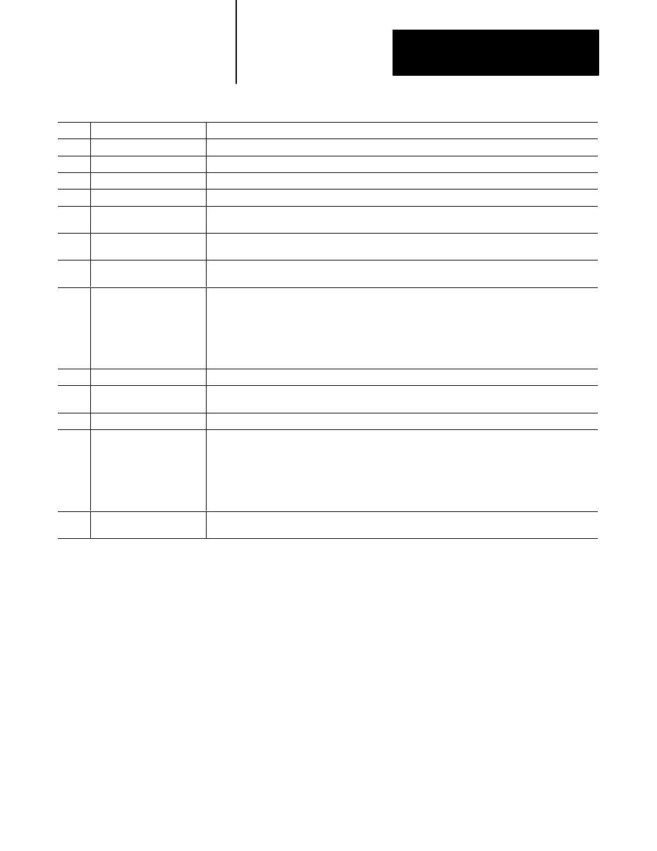
Word
Command
Description
0
Command word
Has value 0001H (to VME) or 0002H (from VME).
1
Response word
As defined previously for all commands in common. See page 3-9.
2
Command interrupt level
As defined previously for all commands in common. See page 3-9.
3
Command interrupt status/ID
As defined previously for all commands in common. See page 3-9.
7
Enable
If 0, none of the subsequent fields are interpreted and the currently defined copy-to-VME (or from-VME)
operation is disabled. If 1, this command establishes a new copy-to-VME or copy-from-VME operation.
7
Width
This defines the data width used to perform reads and writes to VME for the copy operations.
0 denotes D16 and 1 denotes D08(EO).
7
Address modifier
This defines the address space in which the VME data are accessed. Only two values are valid: 2D (A16)
and 3D (A24 or data falls in PLC-5/VME processor’s slave memory).
8-9
Data address
This specifies the VME address at which data transfer is to begin. Bits 23-16 of the A24 VME address are in
bits 7-0 of word 8, and bits 15-0 of the VME address are in word 9. If A16 is specified, word 8 is unused and
word 7 contains the A16 address.
If the PLC-5/VME processor’s slave memory is enabled, if A24 is specified, and if this address falls into
where the slave memory is mapped, the data is transferred into the slave memory without performing any
VMEbus accesses. Otherwise, the PLC-5/VME processor does the transfer as a VMEbus master.
10
Data size
This specifies the number of 16-bit words to be transferred.
11
Data table file number
This specifies the file number of the PLC-5/VME processor’s data table file to or from which data is to
be transferred.
12
Element number
This specifies the element number in the data table file at which the transfer is to begin.
13
Op interrupt level
If nonzero, specifies the VMEbus interrupt to be generated upon completion of each copy operation.
000 specifies no interrupt,
001 specifies interrupt level 1,
010 specifies level 2,
...,
111 specifies level 7.
14
Op status/ID
If an end-of-each-copy interrupt is specified in the previous field, this field is the status/ID value returned by
the PLC-5/VME processor as a result of the corresponding interrupt-acknowledge cycle.
Notes on Copy Operations
For convenience of checking by the driver program, the on-going state
of continuous copy is described in the command control register (see
Chapter 3, page 3-6). If this indicates that an error has occurred, the
driver reads the VME status file (via a PCCC command) to obtain the
specific error code.
To change the copy parameters—i.e., to establish a different continuous
copy—in the PLC-5/VME processor, the driver must issue another
command to set bit 8 of element 28 in the VME status file using a PCCC
write operation.