Setup #1, Setup #2 – Rockwell Automation 1785-Vx0B, D17856.5.9 PLC-5 VME VMEbus Programmable Controllers User Manual User Manual
Page 110
Performance and Theory of Operations
Chapter 7
7-5
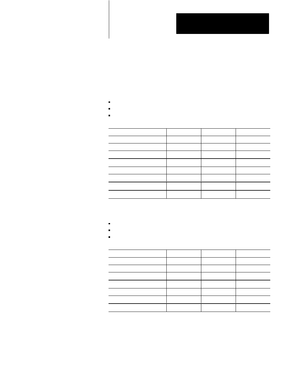
Due to the different loading that can be placed on the communication
processor in the PLC/5 processor, transfer times are not consistent every
time. For each test, 20 readings were taken to calculate the numbers. We
present the minimum, maximum, and average values.
Setup #1
NOCV = 1 (VME coprocessor does not constantly read PLC processor)
Copy to global VME RAM on-board the PLC processor at 0xA00000
Programming terminal not attached to PLC processor
Command
Minimum msec.
Maximum msec.
Average msec.
CTV #N7:0 A0000 D16 1
4.0
8.0
5.0
CTV #N7:0 A0000 D16 500
8.0
9.0
8.0
CTV #N7:0 A0000 D16 1000
12.0
13.0
12.0
CFV A0000 D16 #N7:0 1
4.0
7.0
5.0
CFV A0000 D16 #N7:0 500
8.0
9.0
8.0
CFV A0000 D16 #N7:0 1000
12.0
13.0
12.0
SVE 1 55
3.0
8.0
3.0
CSF
4.0
5.0
4.0
Setup #2
NOCV = 1 (VME coprocessor does not constantly read PLC processor)
Copy to global VME RAM on-board the PLC processor at 0xA00000
Programming terminal attached to PLC processor monitoring ladder file
Command
Minimum msec.
Maximum msec.
Average msec.
CTV #N7:0 A0000 D16 1
4.0
16.0
6.0
CTV #N7:0 A0000 D16 500
8.0
17.0
11.0
CTV #N7:0 A0000 D16 1000
12.0
22.0
14.0
CFV A0000 D16 #N7:0 1
5.0
15.0
7.0
CFV A0000 D16 #N7:0 500
8.0
18.0
12.0
CFV A0000 D16 #N7:0 1000
12.0
17.0
13.0
SVE 1 55
3.0
14.0
5.0