Vme signal usage, Chapter 3 – Rockwell Automation 1785-Vx0B, D17856.5.9 PLC-5 VME VMEbus Programmable Controllers User Manual User Manual
Page 41
Chapter 3
VMEbus Interface
3-3
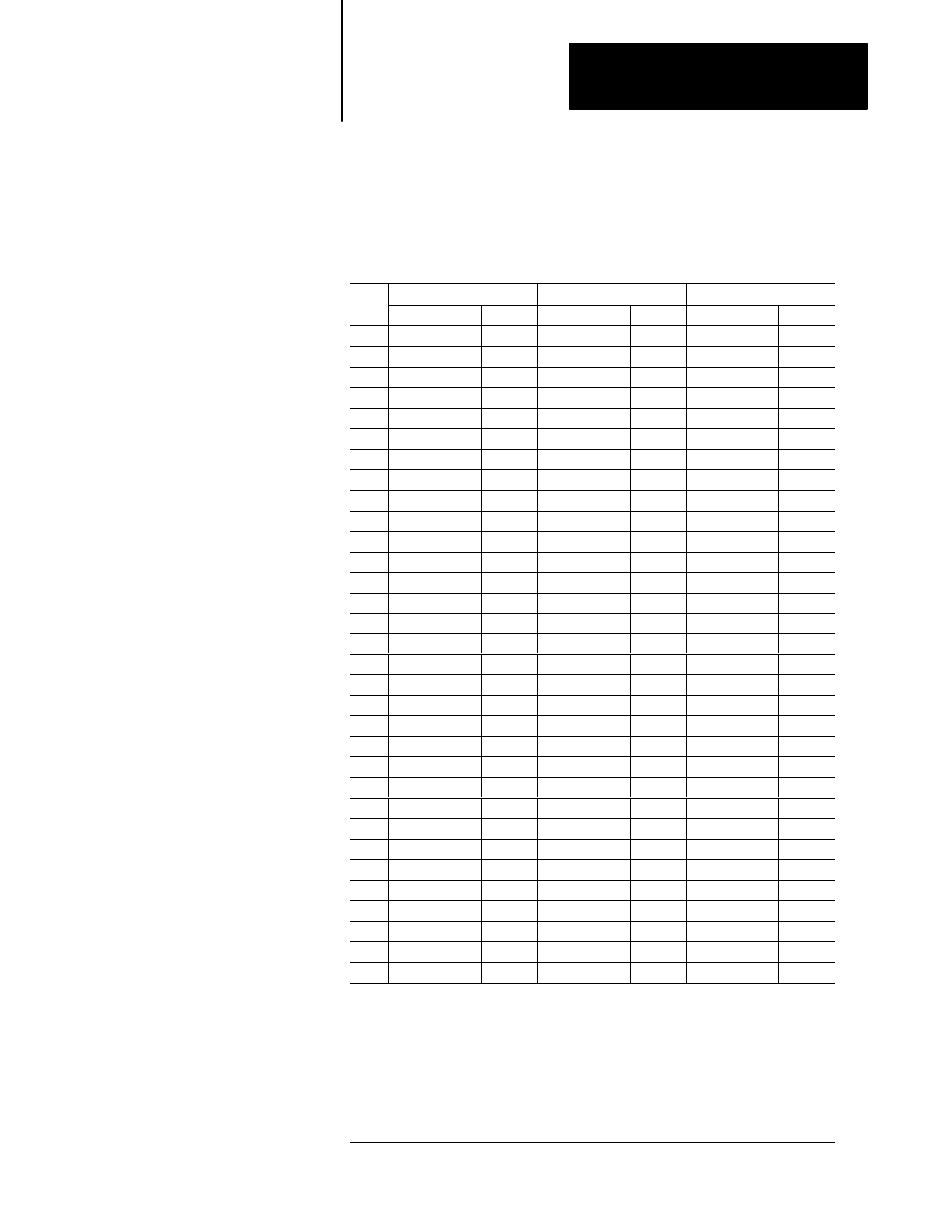
Table 3.A shows the usage of the VMEbus signals on the P1 connector.
Table 3.A
VMEbus Signals on the P1 Connector
Row A
Row B
Row C
Pin
Name
Use
❷
Name
Use
❷
Name
Use
❷
1
D00
IO
BBSY
❶
IO
D08
IO
2
D01
IO
BCLR
❶
I
D09
IO
3
D02
IO
ACFAIL
❶
I
D10
IO
4
D03
IO
BG0IN
❶
I
D11
IO
5
D04
IO
BG0OUT
❶
O
❹
D12
IO
6
D05
IO
BG1IN
❶
I
D13
IO
7
D06
IO
BG1OUT
❶
O
D14
IO
8
D07
IO
BG2IN
❶
I
D15
IO
9
GND
G
BG2OUT
❶
O
❹
GND
G
10
SYSCLK
O
❸
BG3IN*
❶
I
SYSFAIL
❶
IO
11
GND
G
BG3OUT
❶
O
BERR
❶
IO
12
DS1
❶
IO
BR0
❶
SYSRESET
❶
IO
13
DS0
❶
IO
BR1
❶
O
LWORD
❶
IO
14
WRITE
❶
IO
BR2
❶
AM5
IO
15
GND
G
BR3
❶
IO
A23
IO
16
DTACK
❶
IO
AM0
IO
A22
IO
17
GND
G
AM1
IO
A21
IO
18
AS
❶
IO
AM2
IO
A20
IO
19
GND
G
AM3
IO
A19
IO
20
IACK
❶
IO
GND
G
A18
IO
21
IACKIN
❶
I
SERCLK
A17
IO
22
IACKOUT
❶
O
SERDAT
❶
A16
IO
23
AM4
IO
GND
G
A15
IO
24
A07
IO
IRQ7
❶
IO
A14
IO
25
A06
IO
IRQ6
❶
IO
A13
IO
26
A05
IO
IRQ5
❶
IO
A12
IO
27
A04
IO
IRQ4
❶
IO
A11
IO
28
A03
IO
IRQ3
❶
IO
A10
IO
29
A02
IO
IRQ2
❶
IO
A09
IO
30
A01
IO
IRQ1
❶
IO
A08
IO
31
-12V
P
+5VSTDBY
+12V
P
32
+5V
P
+5V
P
+5V
P
❶
indicates a low true signal.
❷
How the signal is used:
I = input; O = output; IO = input/output; P = power; G = ground;
blank = unused and unconnected
❸
Only if the PLC-5/VME processor is configured as the slot-1 system controller. Otherwise logically
unconnected.
❹
BG0OUT and BG2OUT are driven directly by the corresponding BGxIN*’s. This is done so that
you need not worry about the VMEbus backplane jumpers for the leftmost slot occupied by the
PLC-5/VME processor. You should not install the five bus-grant and IACK daisy-chain jumpers in
the leftmost slot.
VME Signal Usage