Chapter 4 – Rockwell Automation 1785-Vx0B, D17856.5.9 PLC-5 VME VMEbus Programmable Controllers User Manual User Manual
Page 56
Chapter 4
Ladder-Program Interfaces
4-9
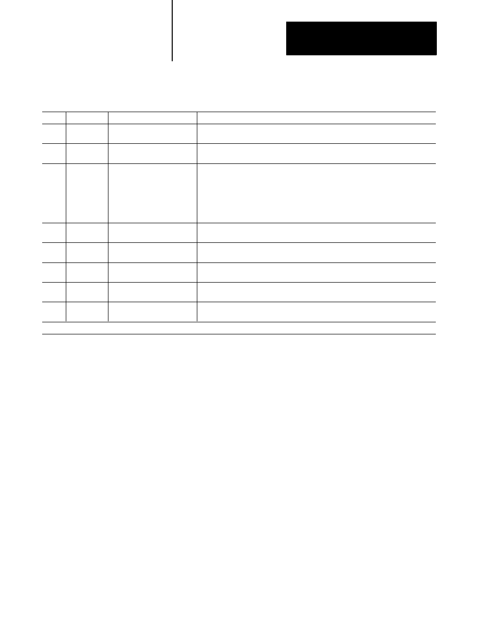
Table 4.B
Fields for the Physical Structure of the VME Status File
Word
Code
Function
Explanation
0
1
VSYSF
Describes the state of the VME
SYSFAIL signal. Read only.
If 0, SYSFAIL is being asserted (including by the PLC-5/VME processor);
if 1, SYSFAIL is not being asserted.
0
1
PSYSF
Read only
Describes the state of the VME SYSFAIL signal as being driven by the PLC-5/VME
processor. If 0, the PLC-5/VME processor is asserting SYSFAIL; if 1, it is not.
1
1
ULA
Unique logical address.
Read only.
The three-switch setting that determines the A16 base address of the PLC-5/VME
processor’s registers.
000 corresponds to FC00,
001 corresponds to FC40,
...,
111 corresponds to FFD0.
1
1
SC
System controller. Read only.
If 1, the PLC-5/VME processor has been configured as the VMEbus slot-1
system controller.
2
1
RELM
VMEbus release mode.
Read only.
If 0, the PLC-5/VME processor has been configured as RWD (release when done);
if 1, the PLC-5/VME processor has been configured as ROR (release on request).
4
1
SLE
Slave enable.
Read only.
If 1, the PLC-5/VME processor’s slave memory in the VMEbus A24 address space has
been enabled.
4
1
SLADDRESS
(HI BYTE)
Read only
Address bits 23-16 of the base address of the PLC-5/VME processor’s slave memory in
the VMEbus A24 address space.
5
1
SLADDRESS
Read only
Address bits 15-0 of the base address of the PLC-5/VME processor’s slave memory in the
VMEbus A24 address space.
1
PLC ladder logic cannot write to statsu file fields that reflect A16 configuration register settings; these fileds are read-only to ladder logic.