Block transfer instructions, Block xfer key method – Rockwell Automation 1772-L8_LW_LWP_LX_LXP,D17726.5.8 User Manual User Manual
Page 448
Quick Reference
Appendix E
E-4
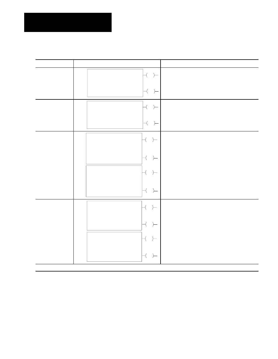
BLOCK XFER Key Method
Key Sequencer
1770ĆT3 Display
Instruction Notes
BLOCK XFER
0
EN
BLOCK XFER WRITE
DATA ADDR:
MODULE ADDR:
BLOCK LENGTH:
FILE:
030
100
01
110Ć110
DN
010
06
110
06
Output instruction.
Block length depends on kind of module.
Entire file transferred in one scan.
Done bit remains on for one scan after valid transfer.
BLOCK XFER
1
EN
BLOCK XFER READ
DATA ADDR:
MODULE ADDR:
BLOCK LENGTH:
FILE:
031
100
01
110Ć110
DN
010
07
110
07
Data read from I/O module must be buffered
Uses two words of user program for each instruction.
BLOCK XFER
0
EN
BLOCK XFER WRITE
DATA ADDR:
MODULE ADDR:
BLOCK LENGTH:
FILE:
030
110
05
200-Ć204
DN
011
06
111
06
EN
BLOCK XFER READ
DATA ADDR:
MODULE ADDR:
BLOCK LENGTH:
FILE:
031
110
05
300Ć304
DN
011
07
111
07
Set block lengths equal or to default value for module.
Enter both instruction blocks for biĆdirectional block transfer.
BLOCK XFER
1
EN
BLOCK XFER WRITE
DATA ADDR:
MODULE ADDR:
BLOCK LENGTH:
FILE:
030
110
05
200Ć204
DN
011
06
111
06
EN
BLOCK XFER READ
DATA ADDR:
MODULE ADDR:
BLOCK LENGTH:
FILE:
031
110
05
300Ć304
DN
011
07
111
07
Same module address used for read and write instruction.
Enable read and write instructions in same scan.
Order of operation determined by the module.
Refer to the module user's manual.
Enter both instruction blocks for biĆdirectional block transfer.
IMPORTANT: Numbers shown are default values. The number of default address digits displayed (3 or 4) will depend on the size of the data table.
Block Transfer Instructions