Rockwell Automation 1772-L8_LW_LWP_LX_LXP,D17726.5.8 User Manual User Manual
Page 314
Bit Shift Registers
Chapter 20
20-4
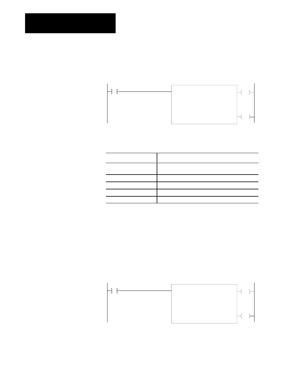
A display represented by Figure 20.2 shows the format of a Bit Shift Left.
Figure 20.2
Bit Shift Left Format
EN
BIT SHIFT LEFT
COUNTER ADDR:
NUMBER OF BITS:
FILE:
INPUT:
OUTPUT:
001
110-110
010/00
010/00
DN
020
10
030
17
030
15
030
Numbers shown are default values. The number of default address digits initially displayed, 3, 4,
or 5 will depend on the size of the data table. Initially displayed default values are governed by the
I/O rack configuration.
This Value:
Stores This:
Counter Address
Address of the instruction in the timer/counter area of the data
table. It represents the accumulated value of the instruction.
Number of Bits
Number of bits in the file.
File
Starting address of the file.
Input
Address of the input bit.
Output
Address of the output bit.
After you enter the following data, the instruction should look
like Figure 20.3.
COUNTER ADDR
200
NUMBER OF BITS
128
FILE
The bit shift register starts and ends at
words 400 and 407 respectively.
INPUT
The input bit is bit 17 of word 130.
OUTPUT
The output bit is bit 00 of word 420.
Figure 20.3
Bit Shift Left Example Rung
EN
BIT SHIFT LEFT
COUNTER ADDR:
NUMBER OF BITS:
FILE:
INPUT:
OUTPUT:
128
400-407
130/17
420/00
DN
020
10
200
17
200
15
200
See chapter 19 for the procedure for using the data monitor. Note that
bit 00 is the right side bit on the file display and bit 17 is on the left.