Rockwell Automation 1772-L8_LW_LWP_LX_LXP,D17726.5.8 User Manual User Manual
Page 230
EAF
Process Control Instructions
Chapter 16
16-19
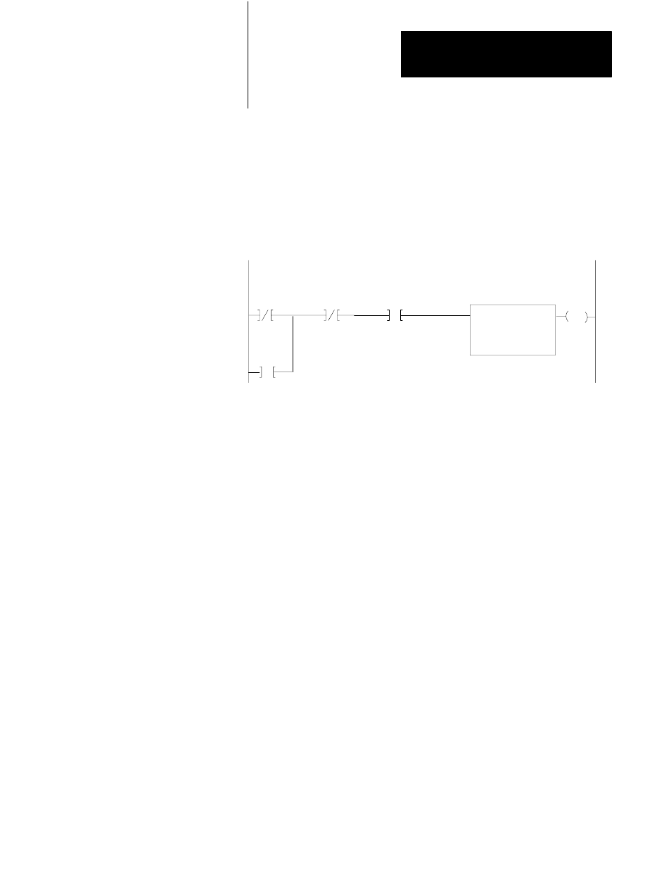
If you are using an 1771-IFE, -IL, -IR or -IXE module, place all module
configuration rungs except rung 2 in the main program. Place rung 2 in the
subroutine. Figure 16.5 shows what the modified STI block transfer looks
like. Please consult the module’s user manual for specific Block Transfer
programming requirements.
Figure 16.5
Initialization Rung
EN
BLOCK XFER READ
DATA ADDR:
MODULE ADDR:
BLOCK LENGTH:
FILE:
0030
100
20
0223
077
Storage
Alternate
Power
Storage
Up
Bit A
Block Transfer Read
Scan Bit
Bit B
Rung 1
Program a Get instruction as the first instruction of the
first rung to indicate that this is a selectable timed
interrupt. The time base is specified by the value in the
Get instruction, in this case, 50 ms.
Bit 077/00 enables the “alternate Scan” PID routines every
other scan. It goes on for one scan and off for the next scan
Rung 2
The BTR instruction executes every other scan.
Rung 3
The Immediate Output Update forces completion of the
BTR instruction.
Rungs
The first four PID instructions grouped with the first
4 – 7
output module.
Rung 8
The BTW for the first 4 PID instructions. The PIDs and the
BTW execute on the same scan.
Rung 9
IOT to force completion of the block transfer.
Rungs
The second four PID instructions grouped with the second
10 – 15
output module block transfer write and the IOT
instructions. The PIDs and the BTW execute on the
same scan.