18ć23, Support rungs – Rockwell Automation 1772-L8_LW_LWP_LX_LXP,D17726.5.8 User Manual User Manual
Page 288
Block Transfer
Chapter 18
18-23
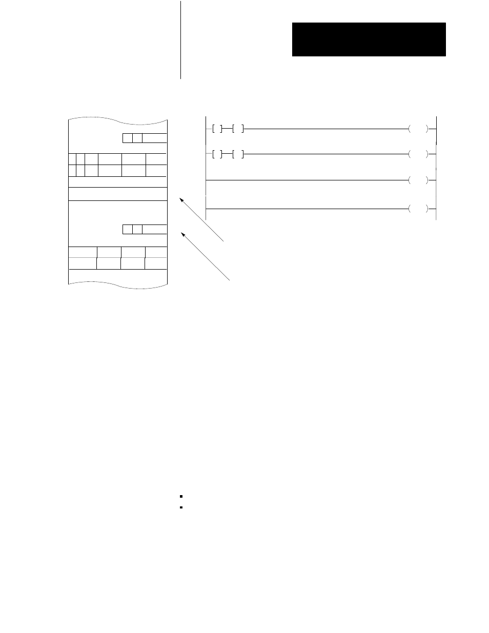
Figure 18.11
Data Table Location for BiĆDirectional Block Transfer
1
1
2
0
3
0
0
5
Block Transfer Write
013
030
050
060
113
130
131
031
030
013
130
G
050
G
130
06
R W
2
0
3
R W
1
1
Block Transfer Read
0
0
6
031
013
131
G
060
G
130
07
030
16
031
17
5 words of data are to be written to the biĆdirectional block
transfer module starting from word 050
8
.
5 words of data are to be read from the module and loaded
into the data table starting at work 060
8
Bit 6 or 7 is set if a successful block
transfer occurred
10383-I
1
1
The second Get instruction of both rungs will be assigned addresses 100
8
words above the first Get instructions. As “data,” they will store the
starting address for block transfer data such as 050 and 060.
The Output Energize instruction is addressed for a write operation in
rung 1 and a read operation in rung 2. To let the processor know whether a
read or write operation is to be performed, bit 16 or 17 of the first Get
instructions must be set On (Figure 18.11). This can be done by
programming an Output Energize or Output Latch instruction
unconditionally. For example, in Figure 18.11 bit 16 of word 030 is set on
to indicate a write operation. Bit 17 of word 031 is set on to indicate a
read operation.
There are additional techniques that can be used to support the block
transfer operation:
Loading Zeros
Setting the number of words to be transferred
Support Rungs