Rockwell Automation 1772-L8_LW_LWP_LX_LXP,D17726.5.8 User Manual User Manual
Page 313
Bit Shift Registers
Chapter 20
20-3
If the bit shift register of Figure 20.1 is 123 bits long, shifting ends at
bit 12 of word 407. In this case, bits to the left of bit 12 in word 407 are
not used for the bit shift register. However, they cannot be used for any
other purpose. The value in bit 123 is shifted directly into output bit B
when a bit shift occurs as shown by the dotted line in Figure 20.1.
The instruction operates in the complete mode. The status of the input bit
is shifted into the first bit in the register and the status of the last bit in the
register is shifted into the output bit in one scan.
Here are some characteristics of the Bit Shift Left instruction:
Programmed as an output instruction
Key sequence [Shift] [Reg] [1] [2]
The counter is internally indexed and externally controlled by the ladder
diagram logic in your program.
Operates in complete mode
Programming a Bit Shift Left Instruction
ATTENTION: The counter address specified for the Bit Shift
Left instruction should be reserved for that instruction only. Do
not manipulate the counter preset or accumulated values.
Inadvertent changes to these values could result in hazardous or
unpredictable machine operation or a run time error. Damage to
equipment and/or personal injury could result.
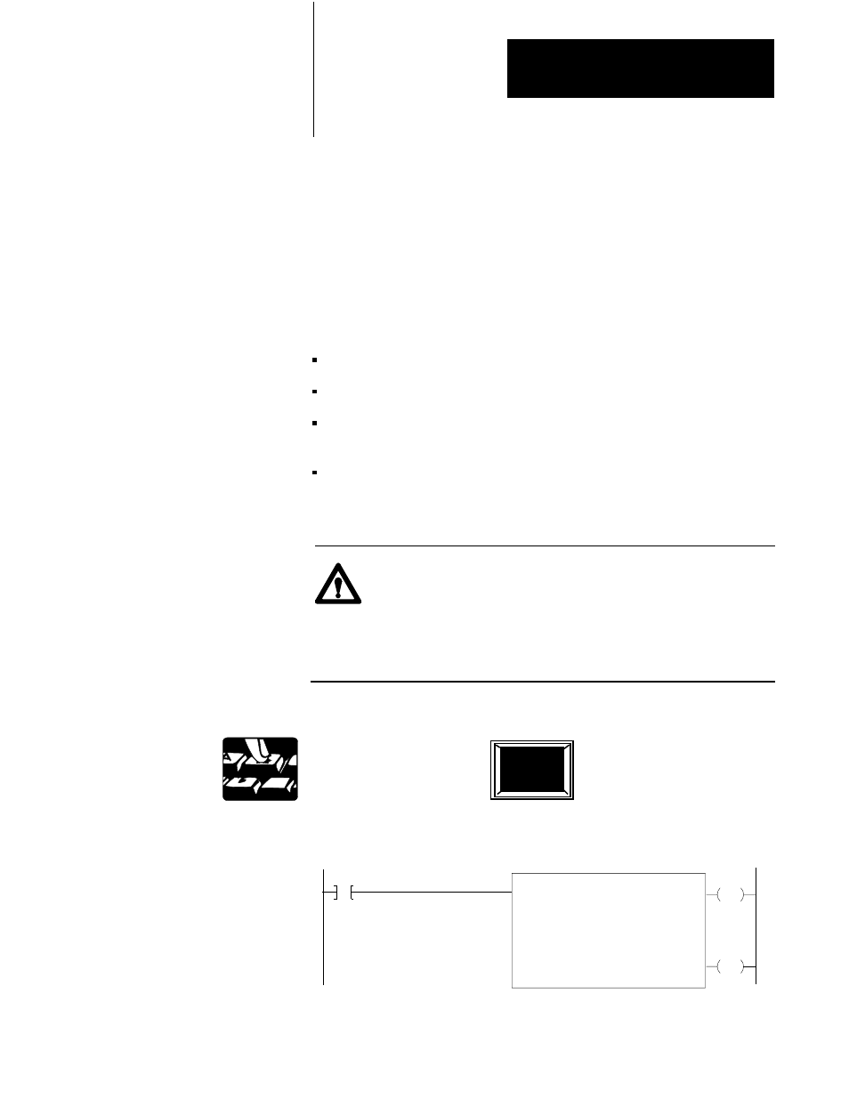
To program a Bit Shift Left instruction:
The prompt SHIFT REGISTER 12 appears in the lower left hand corner of
the screen.
EN
BIT SHIFT LEFT
COUNTER ADDR:
NUMBER OF BITS:
FILE:
INPUT:
OUTPUT:
001
110-110
010/00
010/00
DN
020
10
030
17
030
15
030
12