Scaling – Rockwell Automation 1756-OF8I ControlLogix Eight-channel Isolated Analog I/O Modules User Manual
Page 37
Rockwell Automation Publication 1756-UM540A-EN-P - May 2014
37
ControlLogix Isolated Analog I/O Module Features
Chapter 2
Scaling
When scaling, you choose two points along the module’s operating range and
apply low and high values to those points.
For example, if you are using the 1756-IF8I module in Current mode, the module
supports a 0…21 mA actual range capability. But your application uses a 4…20
mA transmitter. Scaling lets you configure the module to return data to the
controller so that a low signal value of 4 mA returns a low engineering value of
0% and a high signal value of 20 mA returns a high engineering value of 100%.
The returned engineering units value is indicated in the
I.Ch[x].Data tag as
.
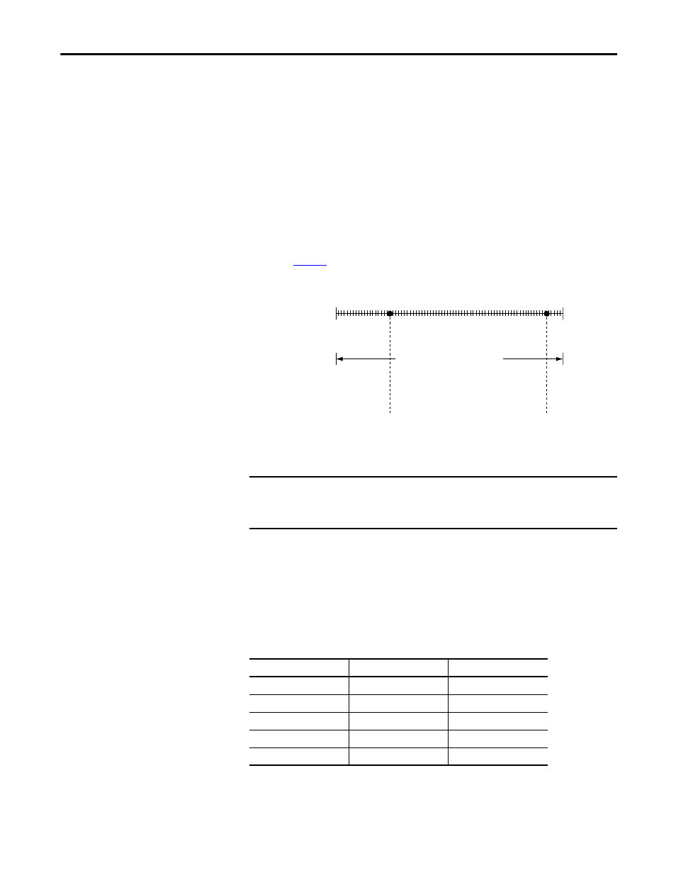
Figure 3 - Module Resolution Compared to Module Scaling
The module can operate with values beyond the 4…20 mA range. If an input
signal beyond the low and high signals is present at the module, for example,
0 mA, that data is represented in terms of the engineering units set during scaling.
The following table shows example values that can appear based on the example
mentioned above.
Module Resolution
5,815,117 counts
0 mA
21 mA
4 mA
20 mA
0% in Engineering
Units
100% in Engineering
Units
Module Scaling
Module scaling represents the data
returned from the module to the controller.
IMPORTANT
In choosing two points for the low and high value of your application, you
do not limit the range of the module. The module’s range and its resolution
remain constant regardless of how you scale it for your application.
Table 3 - Current Values Represented in Engineering Units
Current
Engineering Units Value
Value in I.Ch[x].Data Tag
0.0 mA
-25.00%
-25.00
4.0 mA
0.0%
0.00
12.0 mA
50.0%
50.0
20.0 mA
100.0%
100.0
21.0 mA
106.25%
106.25