Rockwell Automation 22-WIM-N1 DSI Wireless Interface Module User Manual
Page 81
Using RTU Master Mode
D-7
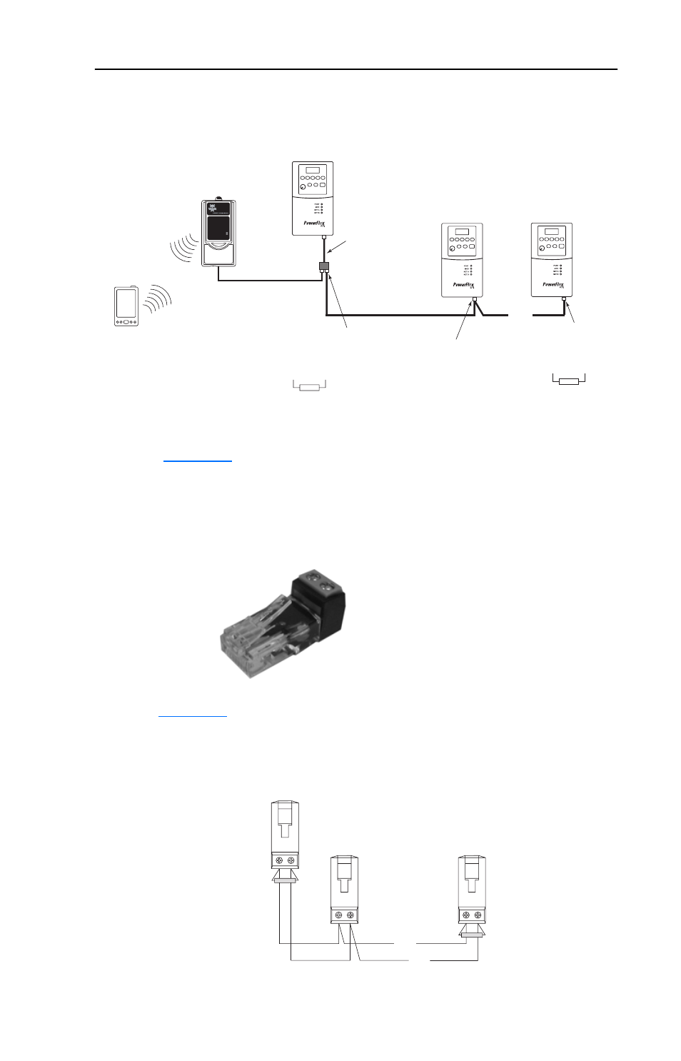
Figure D.7 Wiring Example for RTU Master Network
The AK-U0-RJ45-TB2P two-position terminal block connector
(
Figure D.8
) can be used to conveniently daisy-chain the PowerFlex
4-Class drives from Drive 1, which is connected to the WIM. Two
terminating resistors are also included with terminal block connectors in
the AK-U0-RJ45-TB2P kit.
Figure D.8 AK-U0-RJ45-TB2P Terminal Block Connector
Figure D.9
shows a wiring diagram for using the AK-U0-RJ45-TB2P
terminal block connectors.
Figure D.9 AK-U0-RJ45-TB2P Connector Wiring Diagram
Drive 1
(PowerFlex 4/40/400)
Drive 2
Drive 32
Up to 32 PowerFlex 4/40/400
Drives on RTU Master Network
AK-U0-RJ45-TB2P
Connector with
Terminating Resistor
AK-U0-RJ45-TB2P
Connector
RS-485
. . .
AK-U0-RJ45-SC1
Splitter Cable
AK-U0-RJ45-TB2P
Connector with
Terminating Resistor
HIM Bezel with
Installed WIM
Contains FCC ID: SNT-2XWIMNX
IC: 5450A-2XWIMNX
This device complies with Part 15 of the FCC rules.
Operation is subject to the following two conditions:
1) this device may not cause harmful interference, and
2) this device must accept any interference received,
including interference that may cause undesired operation
Pocket PC,
Laptop or
Desktop
Computer
Master Port
Slave Port
To Slave Port on
Splitter Cable
(connected to Drive 1)
To Drive 2
To Drive 32
120
Ω
¼ Watt
Resistor
120
Ω
¼ Watt
Resistor
. . .
. . .