Rockwell Automation 20D PowerFlex 700S Phase II Drive Frames 1...6 Installation Instructions User Manual
Page 60
60
Rockwell Automation Publication 20D-IN024C-EN-P - July 2013
PowerFlex 700S Adjustable Frequency AC Drive - Phase II Control
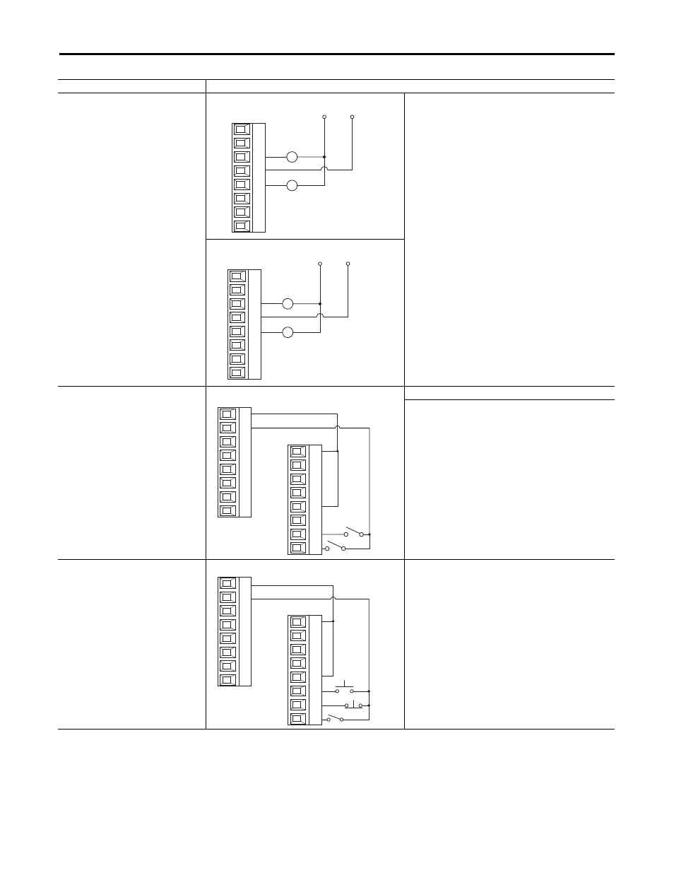
Digital Outputs used with 24V DC Relays -
External Power Supply
Note: Digital Inputs 1-3 are always 12V or 24V
DC.
Sourcing Digital Outputs
• Sourcing a Digital Output - The digital output common
(return) is connected to the power supply common. The device to
be controlled by the digital output is connect to the positive
voltage and the device common is connected to the digital
output.
• Sinking a Digital Output - The digital output common (return)
is connected to the power supply positive voltage. The digital
output is connect to the device to be controlled and the device
common is connected to the power supply common.
Sinking Digital Outputs
Digital Inputs
24V DC
Sourcing Digital Inputs - Internal Power Supply, 2-Wire Control
Required Parameter Changes:
• Set Par 829 [Dig In5 Sel] to value 7 - “Run”.
• Par 153 [Control Options], bit 8 “3WireControl” is automatically
set to “Off” (0) for 2-wire control.
• Set Par 168 [Normal Stop Mode] for the desired stopping mode:
0 = Ramp Stop
1 = CurLim Stop
2 = Coast Stop
Digital Inputs
24V DC
Sourcing Digital Inputs- Internal Power Supply, 3-Wire
• Set Par 829 [Dig In5 Sel] to value 14 - “Normal Stop”.
• Set Par 828 [Dig In4 Sel] to value 5 - “Start”.
• Par 153 [Control Options], bit 8 “3WireControl” is automatically
set to “On” (1) for 3-wire control.
• Set Par 168 [Normal Stop Mode] for the desired stopping mode:
0 = Ramp Stop
1 = CurLim Stop
2 = Coast Stop
Input/Output
Connection Example
24V DC
Common
1
2
3
4
5
6
7
8
24V DC
Common
1
2
3
4
5
6
7
8
24V dc
Com
Run
Enable
1
2
3
4
5
6
7
8
9
10
11
12
13
14
15
16
24V dc
Com
Start
Enable
Stop
9
10
11
12
13
14
15
16
1
2
3
4
5
6
7
8