Figure 3, Figure 3 - bottom views, frames 1…3 – Rockwell Automation 20D PowerFlex 700S Phase II Drive Frames 1...6 Installation Instructions User Manual
Page 17
Rockwell Automation Publication 20D-IN024C-EN-P - July 2013
17
PowerFlex 700S Adjustable Frequency AC Drive - Phase II Control
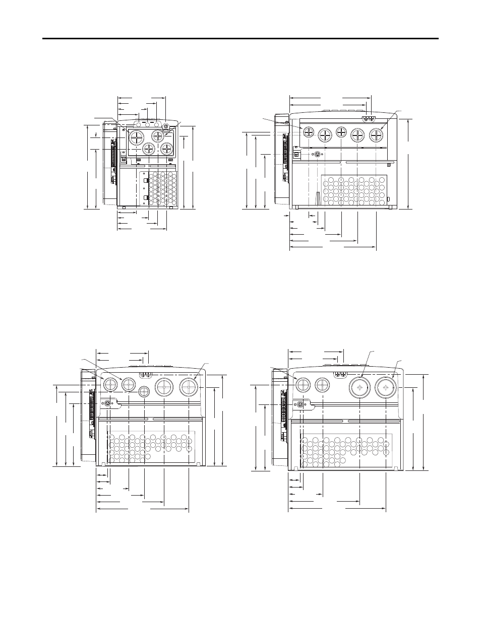
Figure 3 - Bottom Views, Frames 1…3
39.3 (1.55)
57.2 (2.25)
72.7 (2.86)
106.0 (4.17)
139.4 (5.49)
177.4 (6.98)
167.5 (6.59)
156.9 (6.18)
150.9
(5.94)
184.8
(7.28)
157.5
(6.20)
112.1
(4.41)
22.4 (0.88) Dia.
2 Places
28.7 (1.13) Dia.
3 Places
133.3
(5.25)
187.6
(7.39)
25.5
(1.00)
70.0 (2.76)
43.0 (1.69)
96.0 (3.78)
75.9 (2.99)
108.5 (4.27)
67.5 (2.66)
47.5 (1.87)
87.5 (3.44)
22.2 (0.87) Dia.
3 Places
28.6 (1.13) Dia.
185.1
(7.29)
162.3
(6.39)
66.0 (2.60)
94.7 (3.73)
105.3 (4.15)
97.0 (3.82)
137.2 (5.40)
187.0 (7.36)
22.7 (0.89)
29.0 (1.14)
127.7
(5.03)
151.1
(5.95)
160.1
(6.30)
165.1
(6.50)
184.5
(7.26)
22.2 (0.87) Dia.
28.7 (1.13) Dia.
2 Places
37.3 (1.47) Dia.
2 Places
66.0 (2.60)
94.7 (3.73)
105.3 (4.15)
130.0 (5.12)
186.0 (7.32)
22.7 (0.89)
29.0 (1.14)
127.7
(5.03)
160.1
(6.30)
165.1
(6.50)
184.5
(7.26)
28.7 (1.13) Dia.
2 Places
46.7 (1.84) Dia.
2 Places
34.9 (1.37) Dia.
2 Places
Vent Plate
Frame 1
Frame 2
Frame 3 - All Drives, except 50 Hp, 480V (37 kW, 400V)
Frame 3 - 50 Hp, 480V (37 kW, 400V) Normal Duty
Dimensions are in millimeters and (inches)