Step 5: control and i/o wiring, Control and i/o wiring recommendations – Rockwell Automation 20D PowerFlex 700S Phase II Drive Frames 1...6 Installation Instructions User Manual
Page 52
52
Rockwell Automation Publication 20D-IN024C-EN-P - July 2013
PowerFlex 700S Adjustable Frequency AC Drive - Phase II Control
Step 5: Control and I/O
Wiring
Important points to remember about control and I/O wiring:
• Always use copper wire.
• Wire with an insulation rating of 600V or greater is recommended.
• Control and signal wires should be separated from power wires by at least
0.3 meters (1 foot).
• For CE compliance, 115 volt digital input wiring must be shielded or must
not exceed 30 meters (98 feet) in length.
• To maintain electrical safety for all user-accessible low voltage circuits
(SELV and PELV circuits), I/O terminals designated for 24V or lower
voltage must not be connected to a circuit of higher voltage or a circuit
that is not adequately insulated from dangerous voltages with double or
reinforced insulation within other connected equipment or wiring.
• To provide electrical safety for user-accessible low voltage I/O circuits that
are referenced to earth (PELV circuits) and that may be touched
simultaneously, care should be taken to provide a common earth reference
for all equipment connected to the drive.
Control and I/O Wiring Recommendations
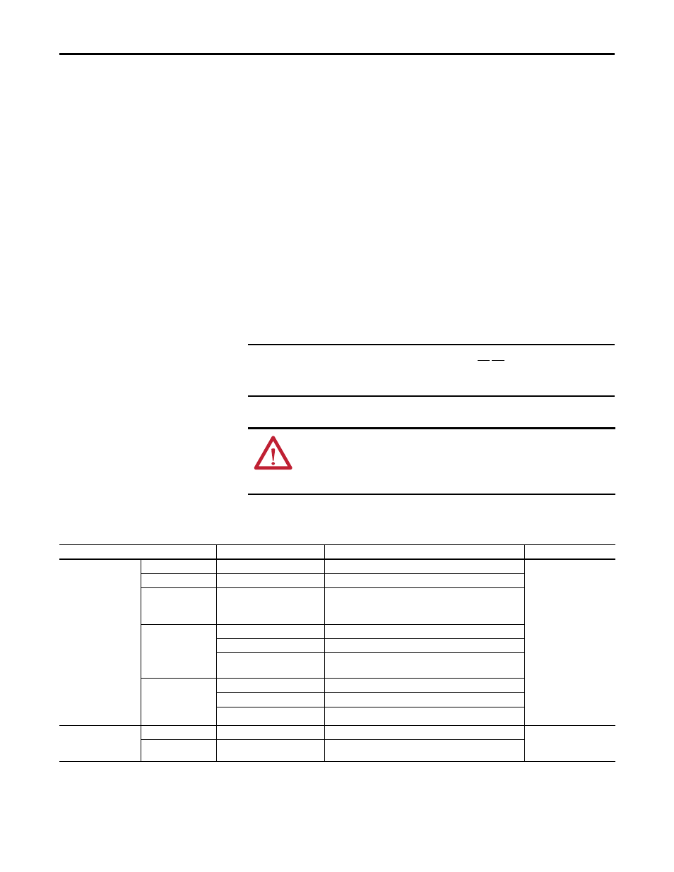
IMPORTANT
I/O terminals labeled “(–)” or “Common” are not referenced to earth ground
and are designed to greatly reduce common mode interference. Grounding
these terminals can cause signal noise.
ATTENTION: Hazard of personal injury or equipment damage exists when
using bipolar input sources. Noise and drift in sensitive input circuits can cause
unpredictable changes in motor speed and direction. Use speed command
parameters to help reduce input source sensitivity.
Type
Wire Type(s)
Description
Min Insulation Rating
Signal
(1) (1) (2)
Standard Analog I/O
–
0.750 mm
2
(18AWG), twisted pair, 100% shield with drain.
300V,
75…90 °C (167…194 °F)
Remote Pot
–
0.750 mm
2
(18AWG), 3 conductor, shielded.
Encoder/
Pulse I/O
<30 m (100 ft)
Combined
0.196 mm
2
(24AWG), individually shielded pairs.
Encoder/
Pulse I/O
30 to 152 m
(100 to 500 ft)
Signal
0.196 mm
2
(24AWG), individually shielded pairs.
Power
0.750 mm
2
(18AWG) in.dividually shielded pairs
Combined
0.330 mm
2
(22AWG), power is 0.500 mm
2
(20AWG) individually
shielded pairs.
Encoder/
Pulse I/O
152 to 259 m
(500 to 850 ft)
Signal
0.196 mm
2
(24AWG), individually shielded pairs.
Power
0.750 mm
2
(18AWG) individually shielded pairs.
Combined
0.750 mm
2
(18AWG) individually shielded pairs.
Digital I/O
Safety Inputs
Homing Inputs
Un-shielded
–
Per US NEC or applicable national or local code.
300V,
60 °C (140 °F)
Shielded
Multi-conductor shielded cable
0.750 mm
2
(18AWG), 3 conductor, shielded.
(1) If the wires are short and contained within a cabinet that has no sensitive circuits, the use of shielded wire may not be necessary, but is always recommended.
(2) I/O terminals labeled “(–)” or “Common” are not referenced to earth ground and are designed to greatly reduce common mode interference. Grounding these terminals can cause signal noise.