Minimum mounting clearances, Figure 1 – Rockwell Automation 20D PowerFlex 700S Phase II Drive Frames 1...6 Installation Instructions User Manual
Page 15
Rockwell Automation Publication 20D-IN024C-EN-P - July 2013
15
PowerFlex 700S Adjustable Frequency AC Drive - Phase II Control
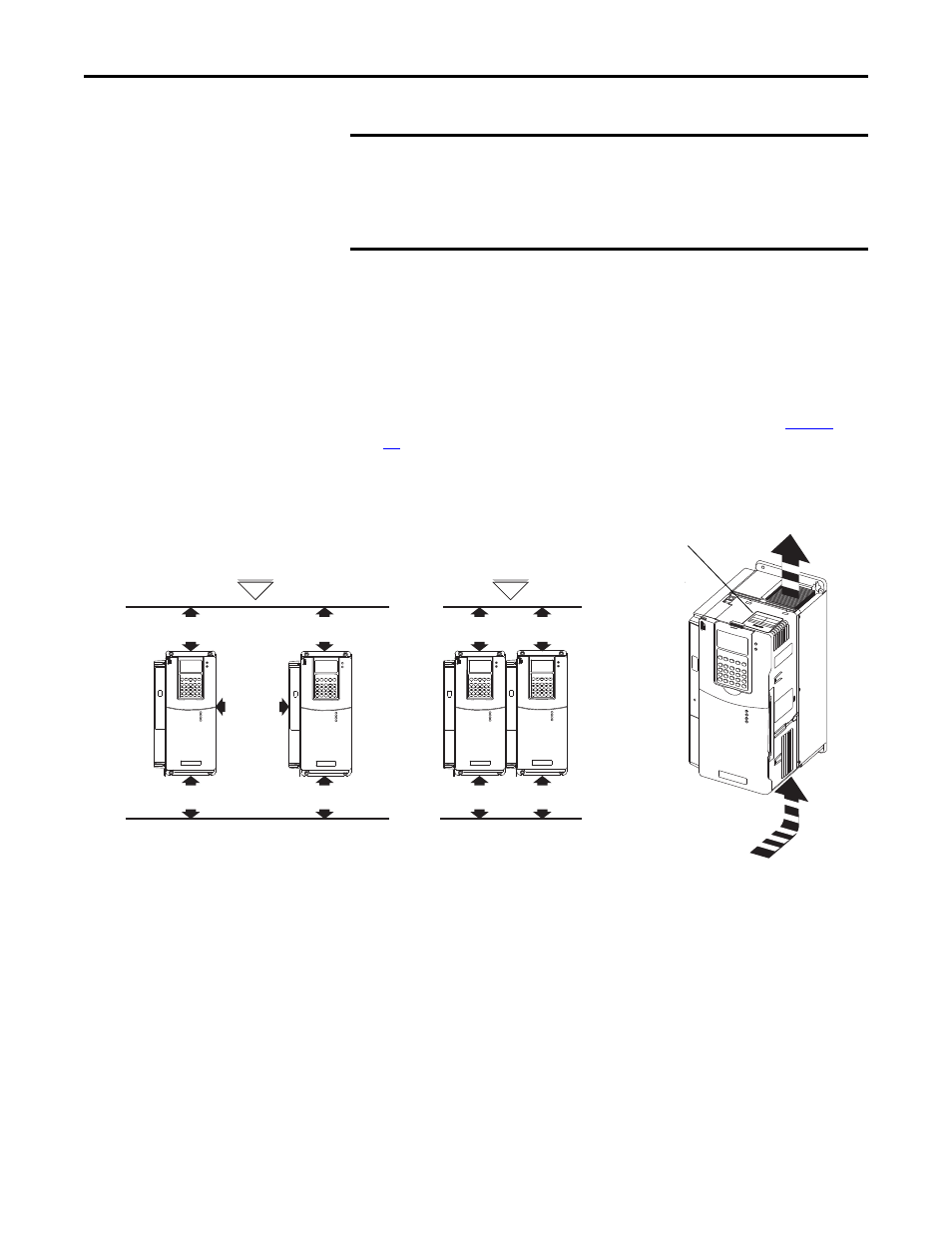
Minimum Mounting Clearances
Specified vertical clearance requirements are intended to be from the drive to the
closest object that can restrict airflow through the drive heat sink and chassis. The
drive must be mounted in a vertical orientation as shown, and must make full
contact with the mounting surface. Do not use standoffs or spacers. In addition,
inlet air temperature must not exceed the product specification. See
page
for ambient air temperature limits.
Figure 1 - Minimum Mounting Clearance Requirements
IMPORTANT
PowerFlex 700S drives must be mounted in a clean, dry location. Contaminants
such as oils, corrosive vapors and abrasive debris must be kept out of the
enclosure. These enclosures are intended for indoor use primarily to provide a
degree of protection against contact with enclosed equipment. These
enclosures offer no protection against airborne contaminants.
50.8 mm
(2.0 in.)
101.6 mm (4.0 in.)
101.6 mm (4.0 in.)
101.6 mm (4.0 in.)
101.6 mm (4.0 in.)
101.6 mm (4.0 in.)
101.6 mm (4.0 in.)
With Adhesive
Label Removed
Adhesive Label
With Adhesive Label
Left in Place
Air flow through the drive
must not be impeded.