Reader installation and wiring, 12vdc power supply e5p e5pw relay module, Electric strike – SDC E5 Series Access Control System User Manual
Page 2: Exit switch
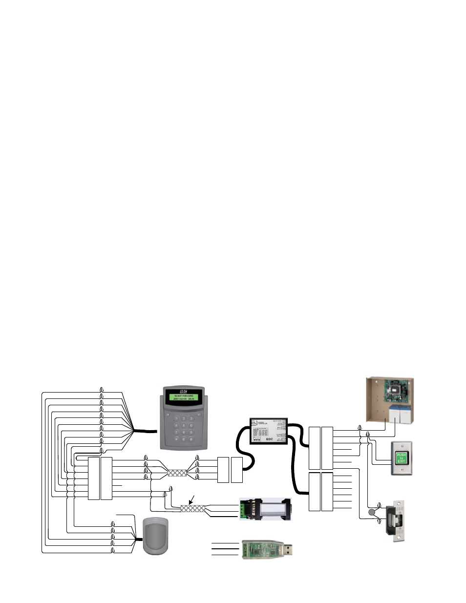
Reader Installation and Wiring
Mounting the Reader:
Use any templates provided to help neatly and securely mount each reader. Remove the
protective plastic sheet from the display window after installation has been completed.
Wiring:
All wire connections must be tight and properly insulated. 2 conductor shielded data cable must
be used for communication wire runs. Power cables must be a minimum size of 22 awg. All cable
types must comply with local building codes. Wiring must be run to avoid sources of EMI
interference such as florescent lighting fixtures or heavy machinery.
Each reader has a separate relay control module. For maximum security, locate this module
inside the secured area. The power supply enclosure for the system is a good choice for module
location.
Power :
Each reader requires a clean regulated source of 12VDC power. Make sure that the power supply
has the capacity to handle the power requirements of the reader and all other equipment
connected to it (eg. slave readers, locks) continuously. If you are powering the lock on the
same power supply as the reader, you must use a MOV across the locks’ coil leads to protect the
readers from spikes and noise.
All wire must be of the proper gauge for the length of the wire run. Excessive voltage drop will
impair the operation and reliability of the installation. Cabling must be in compliance with all
regulations and building codes.
A reliably functioning access control system starts with the proper mounting and wiring of the
readers and associated components. Readers must be securely mounted and all wire
connections must be securely connected and cable runs must be located away from sources of
electrical interference.
BLK
RED
BRN
ORG
YEL
BLK
RED
BRN
ORG
GRN
RED
BLK
GREY
WHT
RED
BLK
GRN
BLU
2
1
3
4
2
1
3
4
BLK
RED
BRN
ORG
YEL
GRN
BLU
GRN
YEL
BLU
YEL
GRN
BLU
2
1
3
4
5
6
7
2
1
3
4
5
6
2
1
3
4
5
6
7
2
1
3
4
5
6
12VDC
+
-
12VDC
POWER
SUPPLY
E5P
E5PW
RELAY
MODULE
(B-)
(A+)
GRN
BLU
RS485/RS232 or RS485/USB
CONVERTER (TO PC)
N/O
N/C
COM
ELECTRIC
STRIKE
(FAIL SECURE)
EXIT
SWITCH
MOV
BLK (GND)
(TR-)
(TR+)
SHIELD
2
1
3
4
5
6
7
2
1
3
4
5
6
7
RED
BLK
BRN
ORG
YEL
GRN
BLU
GREY
WHT
RED
BLK
BRN
ORG
YEL
GRN
BLU
RED
BLK
BRN
ORG
YEL
GRN
BLU
GREY
WHT
VIOLET
VIOLET
VIOLET
WHT
BRN
BLU
(D-)
(D+)
GRN
BLU
BLK (SG)
(+12V)
(-GND)
(DATA 0)
(DATA 1)
(LED)
P:\Installation Instructions\Access Controls\Inst-E5\INST-E5.vsd Rev C 03-13 Page: 1
NOTE: Dual voltage power supplies
Should be switched to 12VDC prior
to hook-up