Danger – MacDon A40-D User Manual
Page 35
SECTION 6 OPERATION
169000 / 169040
33
Revision E
6.6 HEADER
ATTACHMENT:
SELF-
PROPELLED
Refer to your Self-Propelled Windrower
Operator’s Manual for procedures for
mechanically attaching the auger header to the
self-propelled windrower, and for modifications if
required to the windrower hydraulic connections.
Refer to the following procedures for electrical
and hydraulic connections. Header drive
hydraulic hoses and electrical harness are
located on the LH cab-forward side of the
windrower.
6.6.1 A30-S
6.6.1.1
M100, M105, M150, M200 M155
The M100, M105, M150, and M155 Windrowers
are factory-equipped with A30-S header
hydraulics and electrical harness. Proceed as
follows:
DANGER
Stop engine, and remove key from ignition
before leaving Operator's seat for any
reason. A child or even a pet could engage
an idling machine.
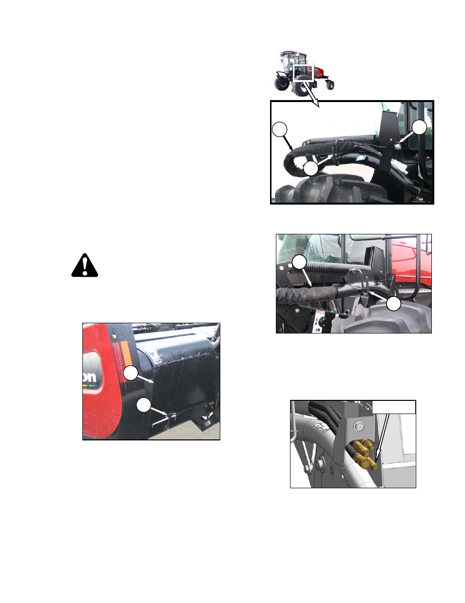
a. Disengage
rubber
latch
(A), and open driveline
shield (B).
b. Remove the cap (C) from electrical connector,
and remove connector from support bracket.
c. Disengage and rotate lever (D) counterclockwise
to fully up position to release the hose bundle
(E).
d. Move hose bundle (E) to header.
e. Rotate lever (D) clockwise, and engage in
bracket to store.
IMPORTANT
If the hose bundle contains four hoses
(draper header operation), only three are
required to power the A30-S header.
Ensure loose hose is properly secured to
avoid contact with the drivelines.
(continued next page)
A
B
D
E
NOT USED
D
C
E