MacDon A40-D User Manual
Page 144
SECTION 7 MAINTENANCE AND SERVICING
169000 / 169040
142
Revision E
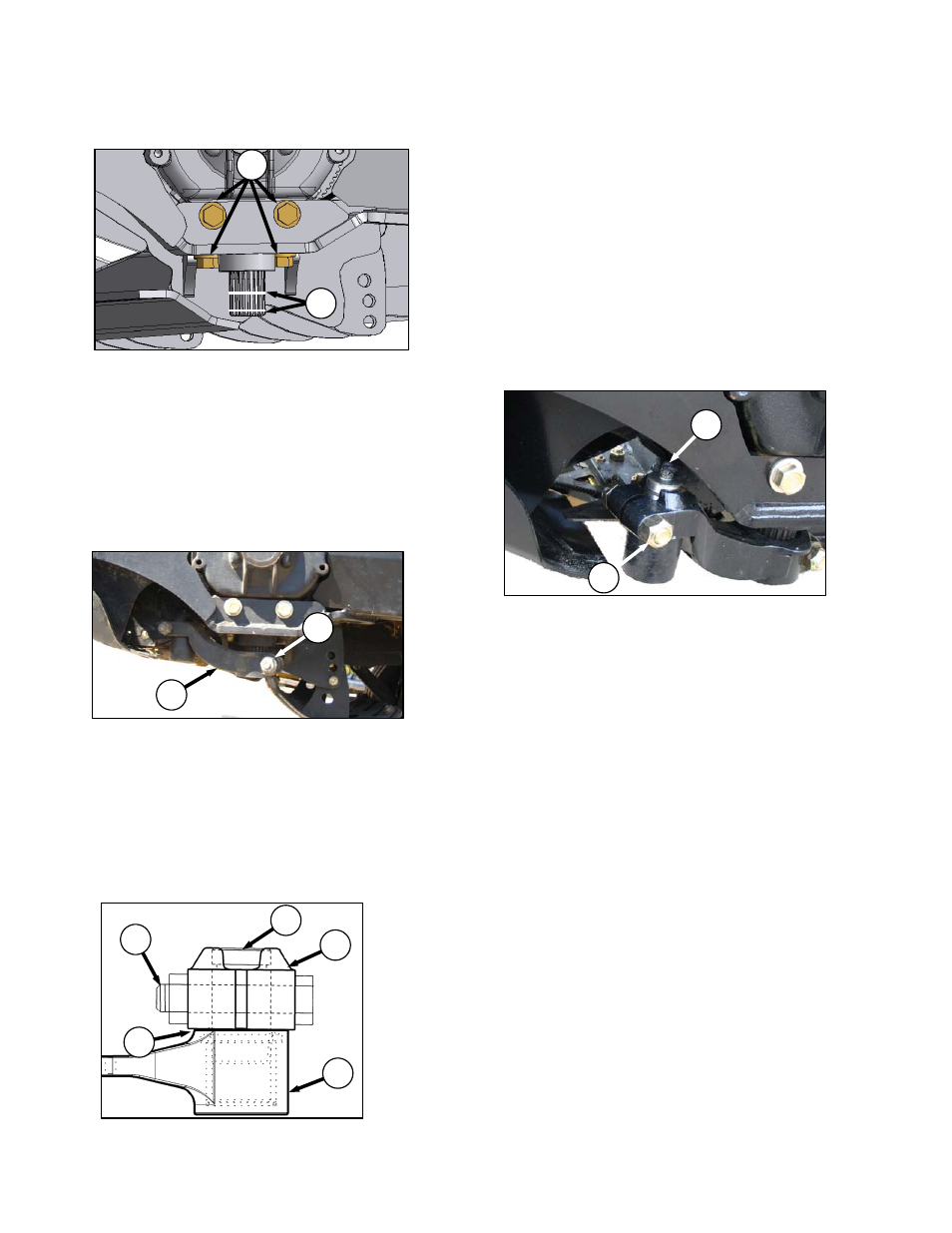
7.8.13.3 Sickle Drive Box Installation
a. Position sickle drive box as shown, and install
four bolts (A). Torque side bolts, and then
torque bottom bolts to 200 ft·lbf (270 Nm).
IMPORTANT
Use only Grade L9 bolts and flat washers.
b. Apply Loctite® #243 adhesive (or equivalent) in
two bands (B) around shaft as shown, with one
band at end of shaft, and one band
approximately mid-way.
c. Slide pitman arm (C) onto sickle drive box output
shaft.
d. Rotate sickle drive box pulley to ensure pitman
arm just clears frame to ensure proper
placement on splines. Remove arm (C), and
re-position on splines as required.
e. Rotate sickle drive box pulley to locate pitman
arm at furthest outboard position.
f. Slide arm (C) up or down on shaft until it just
contacts sickle head (D) (0.010 in. [0.25 mm])
gap.
g. Install bolt (E) and nut, and torque to 160 ft·lbf
(217 N·m).
h. Align sickle head (D) with pitman arm (C).
i.
Install sickle head pin (F) in pitman arm (C) and
tap it down into the sickle head, ensuring pin is
bottomed out in the sickle head.
j.
Tap underside of the sickle head until the pin is
flush with the upper face of the pitman arm (C).
k. Carefully adjust to achieve a 0.010 in. (.25 mm)
gap at (G) with the sickle laying flat on the first
few guards.
l.
Replace bolt (H) and nut.
m. Tighten nut to 160 ft·lbf (220 N·m).
n. Replace grease zerk (J) in pin.
o. Install drive belt onto sickle drive box pulley and
tighten. Refer to one of the following sections,
depending on your equipment:
Section 7.8.9.1 Tension Adjustment: Sickle
Drive Belt - A30-S
Section 7.8.10.1 Tension Adjustment:
LH Sickle Drive Timing Belt - A30-D
Section 7.8.10.4 Tension Adjustment:
RH Sickle Drive Timing Belt - A30-D
Section 7.8.11.1 Tension Adjustment:
LH Sickle Drive Belts - A40-D
Section 7.8.11.4 Tension Adjustment:
RH Sickle Drive Belt - A40-D
A
B
C
E
J
H
C
F
H
G
D