Caution – MacDon A40-D User Manual
Page 141
SECTION 7 MAINTENANCE AND SERVICING
169000 / 169040
139
Revision E
7.8.12 Sickle Drive Timing Adjustment
Double knife A30-D and A40-D Auger Headers
require that the sickles are properly timed to
move in opposite directions.
CAUTION
Stop engine, and remove key from ignition
before leaving Operator's seat for any
reason. A child or even a pet could engage
an idling machine.
a. Remove the right side sickle drive belt. Refer to
Section 7.8.10.5 Removal: RH Sickle Drive
Timing Belt: - A30-D, or Section 7.8.11.5
Removal: RH Sickle Drive Belt - A40-D.
b. Rotate LH side sickle drive box driven pulley (A)
clockwise until LH side sickle (B) is at the center
of the inboard stoke (moving towards center of
header).
NOTE
Center stroke is when the sickle
sections are centered between guard
points as shown.
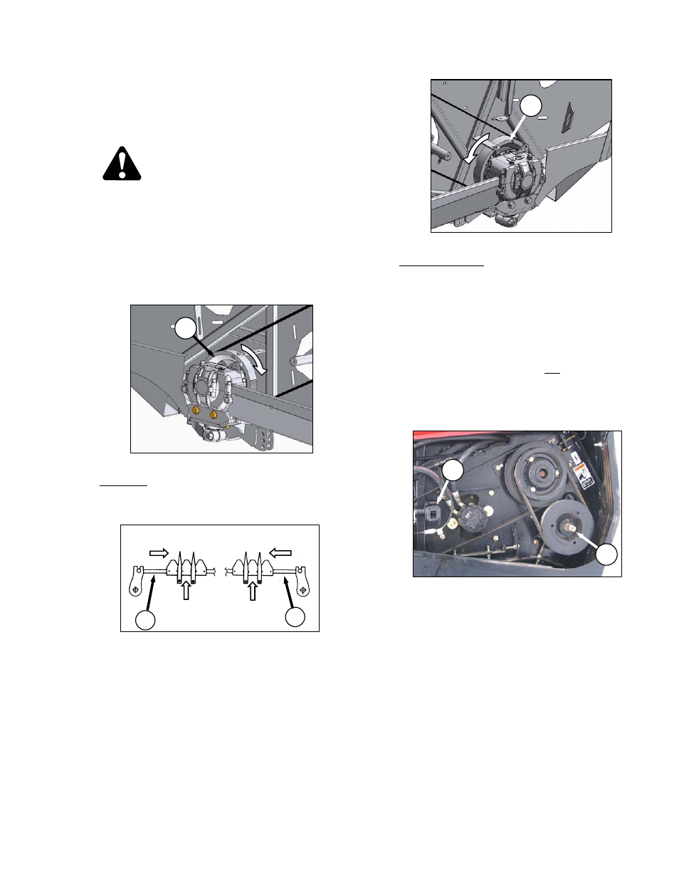
c. Rotate right side sickle drive box pulley (C)
counterclockwise until right side sickle (D) is at
the center of the inboard stroke.
d. Install right side sickle drive box drive belt and
tension. Refer to Section 7.8.10.6 Installation:
RH Sickle Drive Belt - A30-D, or 7.8.11.6
Installation: RH Sickle Drive Belt - A40-D.
IMPORTANT
To maintain timing, sickle drive box driver
and driven pulleys must not rotate as the
belt is tightened.
e. Check that timing belts are properly seated in
the grooves on both driver and driven pulleys.
f. Check for correct sickle timing by rotating
driveshaft (E) slowly with the unplug wrench (F),
and observe sickles where they overlap at the
center of the header.
IMPORTANT
Sickles must move in opposite directions,
and must begin moving at exactly the
same time.
(continued next page)
F
E
RIGHT
SICKLE
LEFT
SICKLE
DIRECTION OF
MOVEMENT
SECTIONS CENTERED
BETWEEN GUARDS
B
D
A
C