Snap-loc 24, Installation of panel, Cont.) – Metal Sales Snap-Loc 24 Installation User Manual
Page 35: Caution, Steps
© Metal Sales Manufacturing Corporation / Subject to change without notice. 10/99
SNAP-LOC 24
34
INSTALLATION OF PANEL
(CONT.)
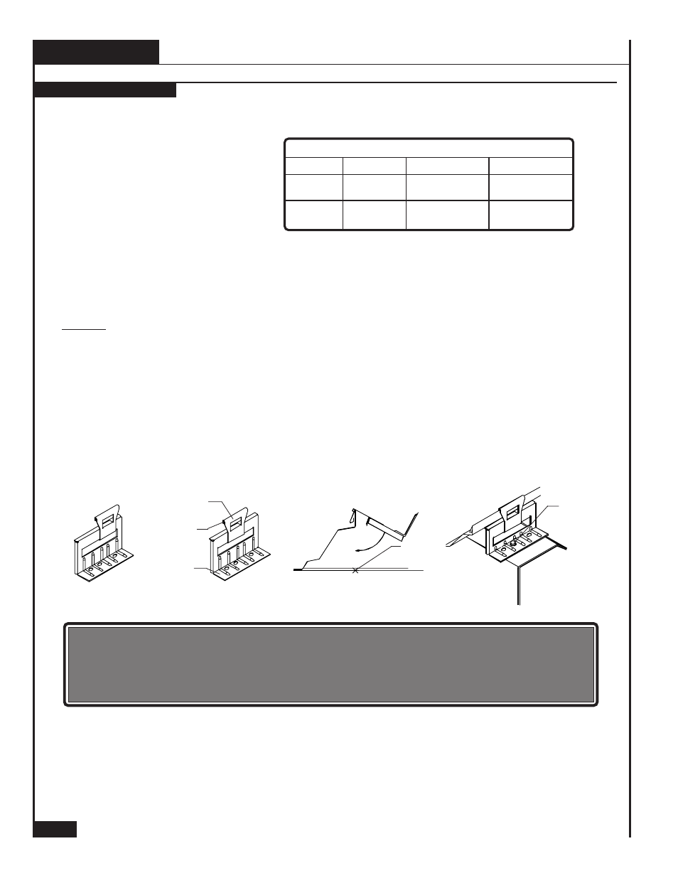
INSTALLING PANEL CLIPS
6. Clips should be installed at all purlin intersections. Panel clips are not required at eave framing
members.
7. As installing clips along the male leg of the panel, measure across the panel to confirm
modularity.
8. If installing over insulation, some method of finding the purlins for clip location must be used.
Insulation should be installed as panels are installed allowing for ease of locating purlins.
CAUTION
If a fastener strips out, you must remove the clip and reposition it so the fastener can drill a
new hole at least 3/8" from the stripped hole or install an oversized fastener in the stripped
hole. Failure to do this will result in weakening the roof wind uplift resistance.
Design wind uplift requirements must be considered for proper placement of clip and spacing.
BASE
SEALANT
VERTICAL TAB
CLIP
FASTENER
CORRECT
INCORRECT
Refer to the chart for
determination of the proper
clip size. Correct clip size
must be used for panel
system to function properly.
It is important to maintain 24" increments between panel clips along the same framing member
as the panel clips control panel modularity.
The following procedures are based on installing panel clips over steel roof purlins. For fastening
clips to a substructure other than steel purlins, see page 17 for correct fastener selection.
STEPS
1. Center the vertical tab of the clip with the slot in the base, this allows the system to float properly.
2. Apply a bead of Tube Sealant to the underside of the vertical tab of the clip.
3. Place the panel clip over the male leg of the panel and center the base of the clip with the center
of the purlin top flange.
4. Rotate the clip to a vertical position so that the base of the clip rests on the top flange of the purlin
and aligns with clip placement mark.
5. Fasten clip to purlin with one (1) #
1
/
4
-14 x 1
1
/
2
" Self Driller No Washer screw into the 2
ND
hole on
the clip.
CLIP
MARK
ROTATE CLIP
OVER MALE LEG
4" TO 6" BLANKET
1"
LOW
HIGH
SYSTEM COMPONENTS
4" TO 6" BLANKET
NONE REQUIRED
3
1
/
4
" LOW
4
1
/
4
" HIGH
SYSTEM
CLIP
THERMAL BLOCK
INSULATION