Electrical installation, Stop, Ecsxs/p/m/a... ecsee... ecsde... ecsxs/p/m/a – Lenze ECSCExxx Power supply module User Manual
Page 46
Electrical installation
Power terminals
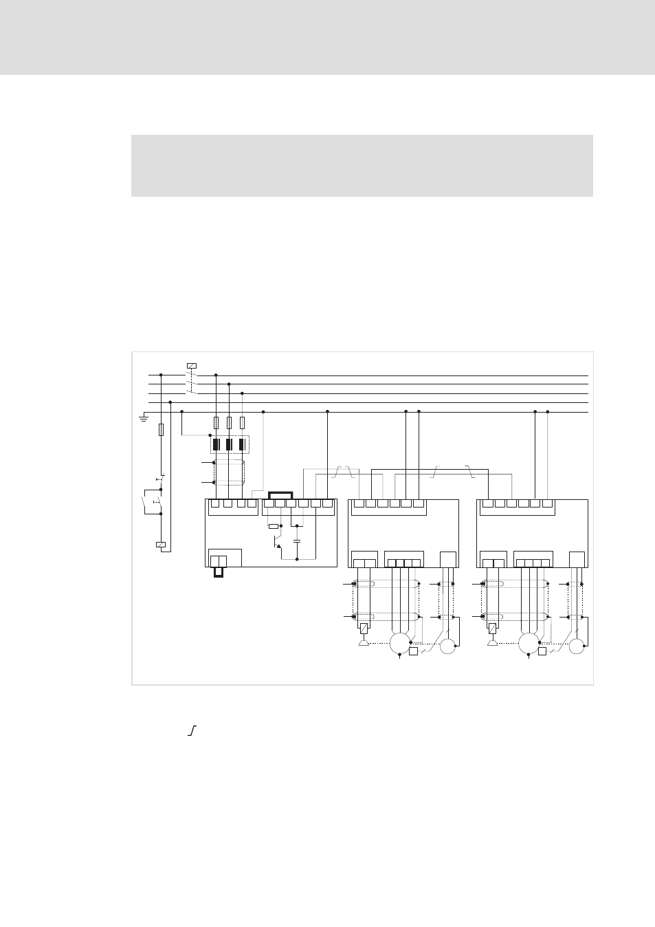
Connection plan for mimimum wiring with internal brake resistor
l
46
EDBCSXE040 EN 7.0
5.3.3
Connection plan for mimimum wiring with internal brake resistor
(
Stop!
Always operate the ECS power supply modules with a brake resistor
(internal/external).
The ECS power supply modules in the standard built−in unit and push−through design
(ECSEE / ECSDE) are provided with a device−internal brake resistor.
In order to use the internal brake resistor (Rb), carry out the following wiring:
ƒ
Bridge between the terminals X22/+UG and X22/BR0 (CR)
Current flow from +UG via the internal brake resistor (Rb) and the brake transistor to
−UG.
ƒ
Bridge between the terminals X6/T1 and X6/T2 (CR)
Deactivate the temperature monitoring of the non−existing external brake resistor.
L3
N
L1
L2
Z1
K1
K1
L1
L2
L3
PE
X21
+UG
+UG +UG
-UG
-UG
-UG
PE
PE
PE
X22
X23
Off
On
+UG
BR1
BR0
M
3~
R
T1
T2
X6
...
J
2
6
K1
0
Rb
U
V
W PE
X24
BD1 BD2
X25
X7
"
"
+
"
"
+UG +UG
-UG
-UG
PE
PE
X23
M
3~
R
J
2
6
0
U
V
W PE
X24
BD1 BD2
X25
X7
+
"
"
"
"
F4
F1...F3
"
"
ECSxS/P/M/A...
ECSEE...
ECSDE...
ECSxS/P/M/A...
ECSXA011
Fig. 5−3
Interconnected power system with internal brake resistor
"
HF−shield termination by large surface connection to functional earth (see mounting
instructions for shield mounting ECSZS000X0B)
Twisted cables
K1
Mains contactor
F1 ... F4 Fuse
Z1
Mains choke / mains filter, optional
Rb
Internal brake resistor
J
KTY thermal sensor of the motor
0
System cable for feedback