4 setpoint value configuration, Setpoint value configuration, 5 configuration – JUMO 709062 TYA 202 - Three-Phase Power Controller Operating Manual User Manual
Page 58
5 Configuration
56
2012-12-31/00561073 [SCR power switch TYA202]
5.1.4
Setpoint value configuration
This setting determines which analog input specifies the setpoint value, how high the
base load is, and which alternative value should be applied in the event of an error.
Value / settings
Description
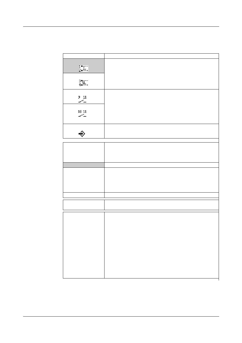
Setpoint input
Current input
This setting specifies which analog input supplies the setpoint
value for the power output.
Note:
These inputs can also be used for logic operation.
v For switching level, see Chapter 10.7 "General char-
Voltage input
Binary input1
Note:
This setting is only available if power controller
r
SCR control
r
Logic (switch) is set.
In this case, the power controller is controlled in the same way
as a solid-state relay (SSR) via binary input 1 or 2:
contact: closed
r
100 % and open
r
0 %
(for control direction set ex works).
Binary input2
Via interface
Means that the setpoint value for the power output is provided
via an interface.
Input in the event of
an error
Current, voltage, and interface input are monitored for errors
(wire breaks or bus errors). This setting specifies which alter-
native value the power controller should use if the default set-
point value is incorrect.
Last value
The last valid value is used ex works.
Voltage input or cur-
rent input
Depending on which input is set for the setpoint selection, the
second free input may appear at this point.
If an error (e.g. wire break) now occurs at the current input,
which is set ex works for the default setpoint value, the power
controller uses the value at the voltage input.
Value, adjustable
This means that the "Value in the event of an error" is used.
Value in the event
of an error
000.0
This value is used in the event of an error.
Maximum actuating
variable
0 to U
nom.
to 1.15 U
n-
om.
of the load voltage,
0 to P
nom.
to 1.15
P
nom.
of the power
0 to I
nom.
of the max. load cur-
rent
0 to 100 %
of the output level
In the case of continuous SCR control via the analog input,
the maximum actuating variable in the master branch at the
measuring range end (e.g. 20 mA) can be varied during opera-
tion.
Note:
This setting is only available if power controller
r
SCR control
r
Continuous (power controller) is set.
The unit depends on the setting for subordinate control loop
and device type:
- U2 and U: display in V (example: 0 to 230 to 264.5 V)
- P: display in W (example: 0 to 4600 to 5290 W)
- I2 and I: display in A (example: 0 to 20 A)
- None: display in % (example: 0 to 100 %)