JLG 340AJ Service Manual User Manual
Page 233
SECTION 5 - HYDRAULICS
3121259
– JLG Lift –
5-75
MARKING THE PARTS
Mark the parts before completely disassembling a pump. The
marks allow components to be reassembled in the same rela-
tive position. This action should be applied to the body, bear-
ings, and gears. Scribing, bluing, or using a felt tip pen to mark
the outside of the body on the inlet side is suggested to indi-
cate the relative position of the front flange and the rear cover
to the body. Mark the bearing blocks also on the inlet side and
the gears position relative to each other. DO NOT scribe inter-
nal surfaces.
PROCEDURE
1.
Clamp the unit.
Clamp the unit in a vice from the flange side.
Make sure the vice jaws are clean and have smooth sur-
faces to prevent damage to the pump.
Clamping the pump on the body is not recommended
because serious damage to the surfaces, on which the
ports are located, may occur.
2.
Remove capscrews.
Use a 17 mm socket wrench and loosen the four cap-
screws on the cover. Next completely unscrew the cap-
screws and remove them.
Inspect the threads of the capscrews for damage.
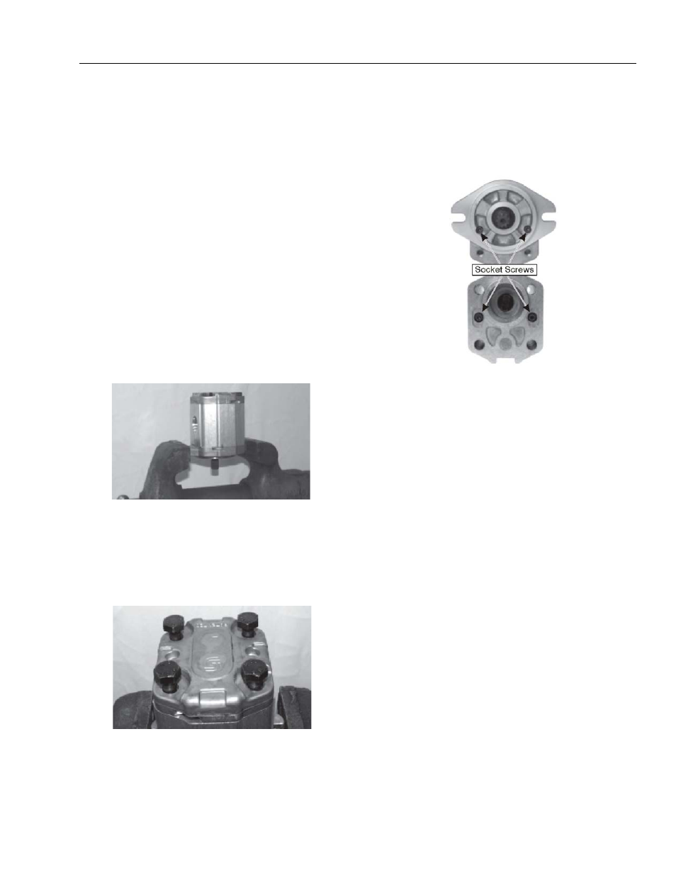
3.
Remove socket head capscrews.
Using a 4 mm internal hex wrench, loosen and remove
the two small socket screws placed in the center of the
cover. Repeat the same operation for the corresponding
screws on the rear flange.