Displacement limiter adjustment data -54 – JLG 340AJ Service Manual User Manual
Page 212
SECTION 5 - HYDRAULICS
5-54
– JLG Lift –
3121259
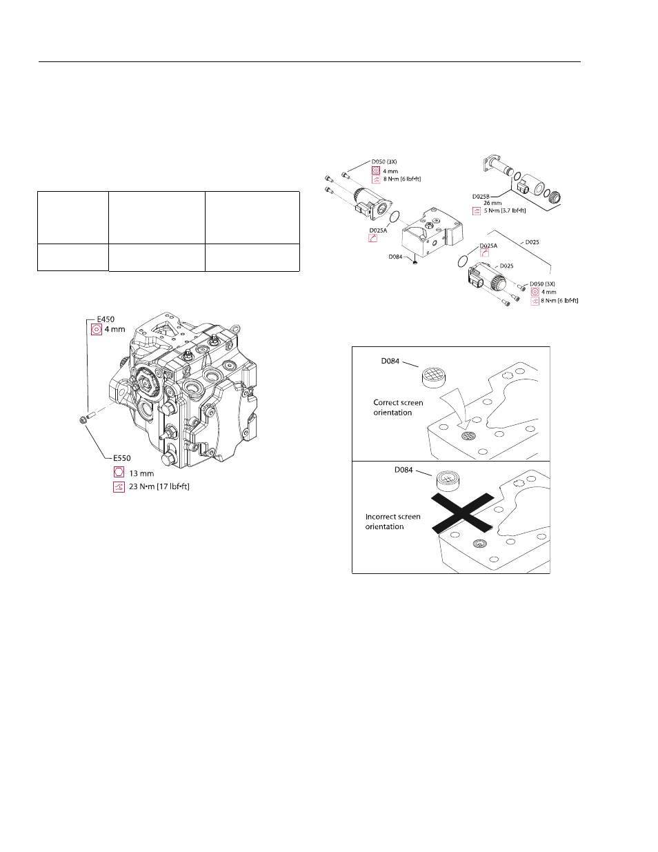
OPTIONAL DISPLACEMENT LIMITER INSTALLATION
NOTE:
Set the approximate displacement limiter depth. See the
table below for displacement change per turn. Run screw
in until it contacts the servo piston, then back out the
appropriate number of turns.
1.
Thread displacement limiter adjusting screw (E450) into
servo sleeve.
2.
Thread a new locking nut onto adjustment screw.Torque
to 23 Nm [17 ft.lbs.] using a 13mm hex wrench.
EDC CONTROL ASSEMBLY
1.
Install new O-rings (D025A) into solenoids (D025), and
attach solenoids with capscrews (D050) using 4 mm
internal hex wrench. Torque to 8 Nm [6 ft.lbs.].
2.
Replace screen (D084) if removed. Drawing shows
proper screen orientation.
NOTE:
If you suspect coil malfunction, remove the coil (D025B) by
removing the plastic nut with a 26 mm 12 point socket.
Install a new coil and torque the nut to 5 Nm [3.7 ft.lbs.].
Table 5-6. Displacement limiter adjustment data
Locknut wrench
size and torque
Adjusting screw size
Approximate
displacement change per
revolution of adjusting
screw
13 mm 23 Nm
[17 ft.lbs.]
4 mm internal hex
5.1 cm
3
[0.31 in
3
]