JLG 340AJ Service Manual User Manual
Page 147
SECTION 4 - BOOM & PLATFORM
3121259
– JLG Lift –
4-15
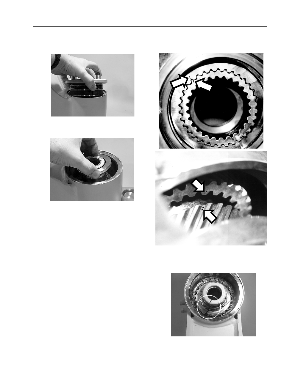
7.
Remove the end cap (4) and carefully set aside for later
inspection.
8.
Remove the stop tube (400) if the actuator is equipped
with one. The stop tube is an available option that limits
the rotation of the actuator.
9.
Every actuator has two sets of small punched timing
marks that indicate timing between the gear sets. The
location and appearance of the marks can vary slightly
between models. One set indicates the timing between
the piston sleeve (3) and the housing (1) (upper photo),
the second set between the piston and the shaft (lower
photo). To ensure correct rotation and accurate end
positions, it is essential that the actuator be correctly
timed when it is reassembled. The punched timing
marks can be used, but it is easier to highlight punched
marks with a marker before disassembly as outlined in
the steps below.
10.
Prior to removing the shaft (2), use a felt marker to
clearly indicate the timing between shaft and piston
sleeve (3). This will greatly simplify timing when the
actuator is reassembled.
- 120HX Service Manual (116 pages)
- 544D-10 Parts Manual (730 pages)
- 100SX Parts Manual (224 pages)
- 450A Operator Manual (68 pages)
- 15DVL (3121839) Parts Manual (126 pages)
- E450 Operator Manual (106 pages)
- E450 Operator Manual (116 pages)
- G5-18A Operator Manual (142 pages)
- 2505H Operator Manual (148 pages)
- 40HA ANSI Parts Manual (322 pages)
- 400RTS Service Manual (100 pages)
- 660SJ Parts Manual (382 pages)
- 660SJ Parts Manual (352 pages)
- 660SJ Parts Manual (310 pages)
- 600S_SJ Parts Manual (299 pages)
- 600S_SJ Parts Manual (302 pages)
- 660SJ Parts Manual (404 pages)
- 660SJ Parts Manual (306 pages)
- 19AMI (3120758) Service Manual (68 pages)
- 500RTS ANSI Service Manual (80 pages)
- 400RTS ANSI Service Manual (98 pages)
- LSS Scissors (78 pages)
- 510AJ Series II Operator Manual (104 pages)
- 800S Operator Manual (158 pages)
- 800S Operator Manual (130 pages)
- 35xxPS Operator Manual (176 pages)
- 400RTS ANSI Operator Manual (48 pages)
- 500RTS ANSI Operator Manual (46 pages)
- 800A_AJ Operator Manual (134 pages)
- 800A_AJ Operator Manual (150 pages)
- 266 Operator Manual (140 pages)
- G9-43A Parts Manual (788 pages)
- G6-42A Parts Manual (478 pages)
- M400AJP Narrow (108 pages)
- E400 Operator Manual (118 pages)
- 80HX_HX+6 ANSI Operator Manual (104 pages)
- 1350SJP Quick Reference Guide (1 page)
- 1350SJP Quick Reference Guide (2 pages)
- 15VPSP (3120798) Parts Manual (98 pages)
- X14J Operator Manual (169 pages)
- 400S ANSI Service Manual (464 pages)
- X17J Plus Operator Manual (176 pages)
- 20AM Operator Manual (98 pages)
- 3369LE Operator Manual (86 pages)
- 3369LE Operator Manual (84 pages)