JLG 340AJ Service Manual User Manual
Page 199
SECTION 5 - HYDRAULICS
3121259
– JLG Lift –
5-41
ALIGNMENT PINS (G450) ARE IN END COVER. THEY MAY DISLODGE DURING
DISASSEMBLY.
3.
Remove and discard gasket (K150).
4.
Remove thrust washer (K500). Note thrust washer orien-
tation.
5.
Remove pressure balance plate (S200) and seal (S300).
Note plate orientation. Discard seal (S300).
6.
Remove coupling (K200).
CHARGE PUMP REMOVAL
1.
Remove charge pump outer ring (S150),and gear-
set(S100).
2.
Remove valve plate (S250) with seal (S300). Discard seal
(S300).
NOTE:
If charge pump requires replacement, replace as a kit. Kit
includes (S300), (S250), (S100), and(S200).
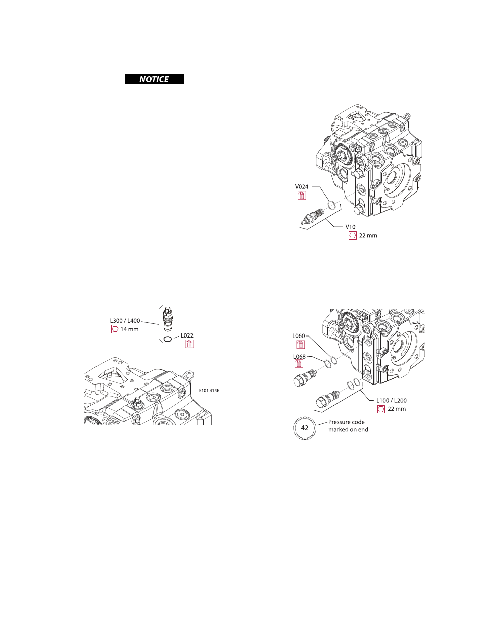
PRESSURE LIMITER REMOVAL
1.
Using a 14 mm wrench, remove pressure limiter car-
tridges (L300) and (L400).
NOTE:
Pressure limiter (L300 / L400) is available as complete unit
only. Seal (L022) is available separately.
2.
Remove and discard O-ring (L022).
NOTE:
Right and left pressure settings are different. Tag each
valve for later re-assembly
CHARGE PRESSURE RELIEF VALVE REMOVAL
Using a 22 mm wrench, remove the charge pressure relief
valve (VI0). Discard O-ring (V024).
NOTE:
Charge pressure relief valve (VI0) is available as complete
unit only. Seal (V024) is available separately.
HIGH PRESSURE RELIEF VALVE REMOVAL
Using a 22 mm wrench, remove the HPRV valves (LI00 / L200).
Discard O-rings (L060) and seals (L068).
NOTE:
HPRV valves may not have the same pressure setting. Tag
each valve for reassembly.