Burnham Series 5B User Manual
Page 69
69
If Burners must be removed, use the following
procedure:
a. Mark location on manifold of all burners with pilots.
b. Using a pair of pliers, remove hitch pin clips
(shaped like a hairpin) from groove in main burner
orifices. SAVE ALL CLIPS.
c. Remove all burners without pilots by lifting front
of burner slightly, then pushing burner toward rear
of boiler until front of burner clears orifice, then
lift rear of burner until head of weld pin on bottom
rear of burner clears keyhole slot in base rear
panel. Burner is now free and can be lifted out thru
opening in base front frame.
d. Remove all burners with pilots by first tracing all
electrical leads coming from pilot to their points of
connection, remove leads from terminals to which
they are connected, and then tag each lead with
respective terminal designation. Disconnect Pilot
Tubing at nearest connection to pilot and remove
burner as outlined in paragraph c. above.
e. When replacing burners, reverse procedure used in
removal of burners. Make sure burners are secure in
keyhole slots in base rear panel and hitch pin clips
are installed in grooves in all main burner orifices.
Burners with pilots must be in same locations as
original installation. If markings placed on manifold
(when burners were removed) are obliterated, see
Fig. 58. Reconnect electrical leads and reconnect
pilot tubing.
Reinstall Flue Cleanout Plates so that they are gas
tight. Reinstall Burner Access Panels and Jacket
Panels.
4.
LUBRICATION
Manufacturers Instruction should be followed on all
parts installed on the boiler that require lubrication.
Generally this involves only the circulator in a hot
water system. This includes:
(a) Type of lubricant to be used
(b) Frequency of lubrication
(c) Points to lubricate
5.
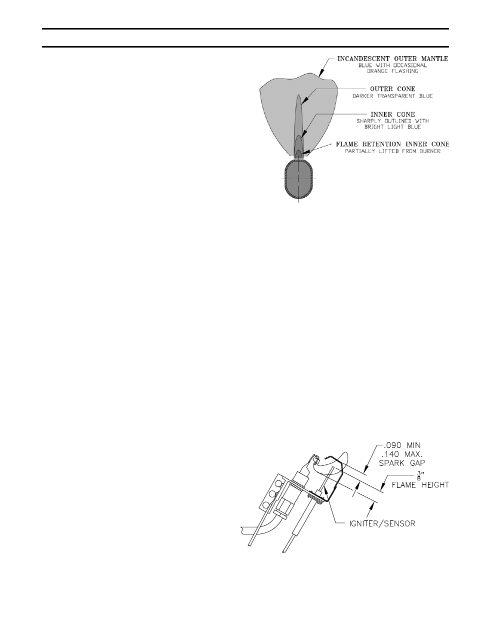
MAIN BURNER FLAMES –
Main Burner Flames should be checked at initial
start-up, annually thereafter, or after flueway cleaning,
or after an extended shutdown period. Main Burner
Flame should have a clearly defined inner cone, see
Fig. 59, with no yellow tipping. Orange-yellow streaks
caused by dust should not be confused with true yellow
tipping.
Yellow-tipping indicates a lack of primary air and
normally can be corrected by opening the air shutter.
Improper alignment of burner on orifice will also affect
primary air injection.
SECTION V – SERVICE (continued)
FIG. 59
MAIN BURNER FLAME ADJUSTMENT
FIG. 60
PILOT FLAME - HONEYWELL Q3481B
6.
PILOT FLAME –
Pilot Flame should be checked at initial start-up,
annually thereafter, or after flueway cleaning, or after
an extended shutdown period.
The EI Control System utilizes a Honeywell Q3481B
pilot. Flame should be adjusted by means of the pilot
line regulator 5.5” WC pilot line press so that a medium
hard center flame envelopes approximately 3/8” of
the end of the sensing probe, see Fig. 60. If flame
is yellow, primary air slot may be covered with dirt
or lint. This can be removed with a soft brush or by
vacuuming.
a. To adjust or check spark gap between electrode and
hood on Honeywell Q3481B intermittent pilot. (See
Fig. 60)
1. Use a round wire gauge to check spark gap.
2. Spark gap should be 0.1” for optimum
performance.
The OP Control Systems utilize a Honeywell
Q179D Flame Rectification Pilot to which a Q309
thermocouple has been added. Adjust pilot line