Burnham Series 5B User Manual
Page 34
34
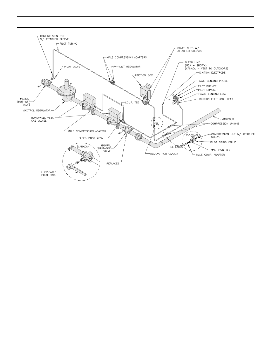
FIG. 33
PILOT PIPING - EI CONTROL SYSTEM (V88A)
U.S.A. 5010B THRU 5026B - NAT. GAS
CANADA - 5006B THRU 5026B - NAT. GAS
4.
COMPLETION OF WIRING – Connect power supply
fused disconnect switch, service switch, primary side
of transformer, gas valves and remaining controls – see
Fig. 42, 43 or 44 for wire type and connections to be
made. All wiring must be adequately supported and
strain relief provided. All wiring including ground
connections must comply with the requirements of
the authority having jurisdiction and, in the absence
of such, to the National Electrical Code, ANSI NFPA
No. 70-2005, or the Canadian Electrical Code, C22.1,
whichever is applicable.
OP Control System
1.
INSTALLATION OF PILOT SAFETY SWITCH AND
PILOT PIPING – Using two #10-32 x 2” MS and nuts,
install the L62GB-3C pilot safety switch bracket on the
manifold just to the right of the main burner with pilot.
Install L62GB-3C pilot safety switch on bracket using
two #8 x ½” SMS. “IN” on pilot safety switch should
be pointed in the direction of the Gas Train to which the
pilot safety switch is to be connected, see Fig. 34.
Using ¼” OD Aluminum Tubing, connect the pilot
valve installed in the manual shut-off valve in the gas
train, to the inlet of the RV-12LT regulator (packed
in gas train carton). Regulator should be above Gas
Train and near front of boiler, see Fig. 35. Install 1/8”
tee into outlet of regulator (USA boilers only) and,
using ¼” OD tubing, connect outlet of tee to “IN”
connection on pilotstat, see Fig. 35. Connect the Q309
thermocouple to pilot safety switch. Using ¼” OD
aluminum tubing, connect the outlet of the pilotstat to
the tubing or fittings connected to the pilot burner, see
Fig. 35.
SecTiON iii – iNSTALLATiON iNSTRUcTiONS (continued)