Warning – Burnham Series 5B User Manual
Page 30
30
A Bottom Blowoff using a valve must also be
connected to one of the return tappings. The ¾”
Drain Valve may be used for Bottom Blowoff for
5009B or smaller boilers, since any Bottom Blowoff
piping or valves for 5009B or smaller boilers must
be at least ¾”. Bottom Blowoff piping and valves
for Boilers 5010B through 5021B must be at least
1”. Bottom Blowoff piping and valves for 5022B
Boilers and larger must be at least 1¼”.
g. If boiler has been ordered with 3/8” try-valve
tapping, install try-cock.
h. Install “Lowest Permissible Water Level Plate”
and “Frequent Water Addition – Caution Label” on
upper left end jacket panel.
i. Proceed directly to Paragraph 36.
34.
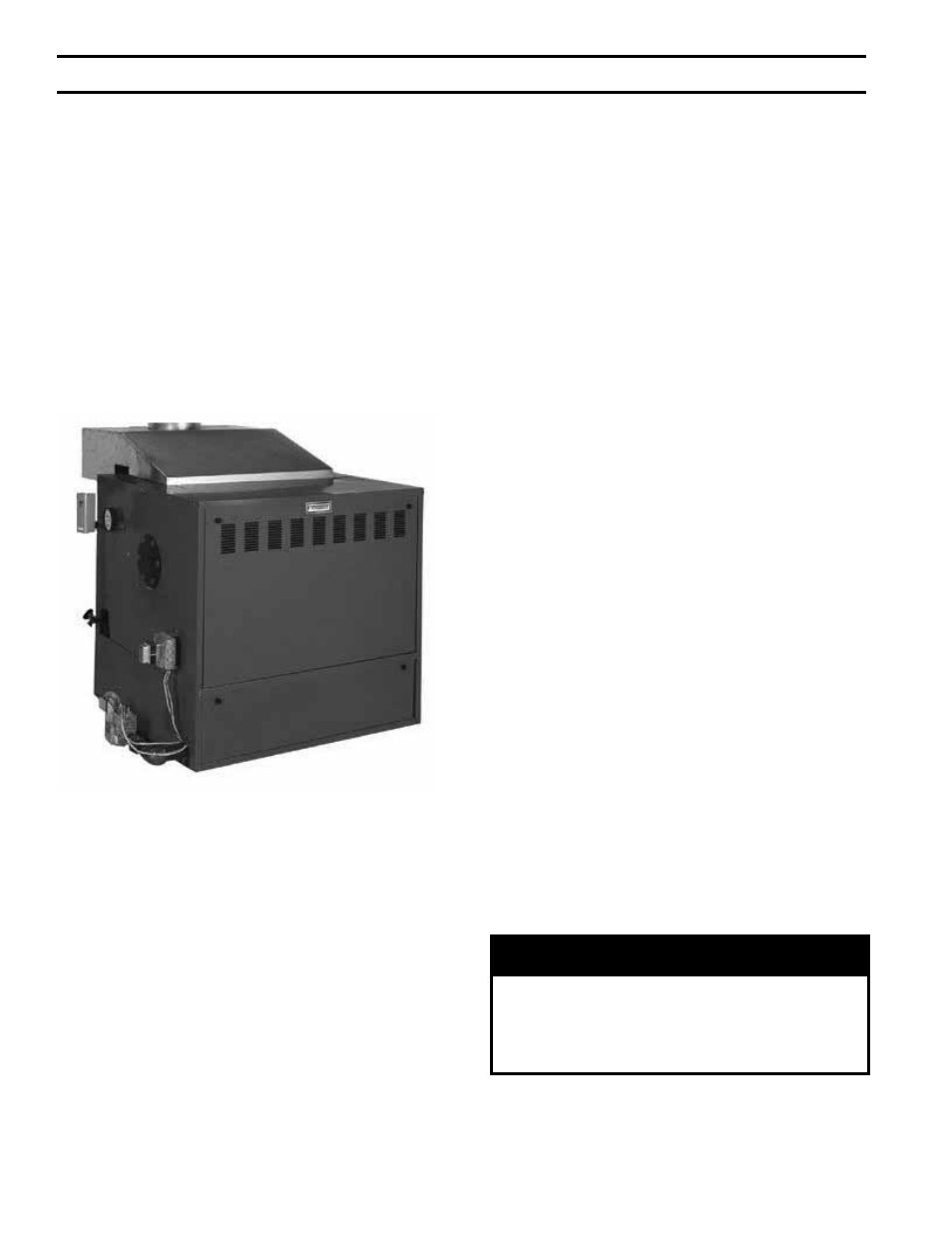
INSTALL WATER TRIM AND CONTROLS, see
Fig. 7 and 29.
a. Temperature Gauge is to be installed with ½”
nipple and ½” x ¼” reducing coupling in ½”
tapping provided in upper corner of End Section
using wrench applied to square shank on back of
gauge. DO NOT APPLY PRESSURE ON GAUGE
GLASS.
b. Install Temperature Limit Controls as follows:
Bush 1-1/2” tapping in upper corner of End Section
to ¾” and install Temperature Limit Control
furnished following instructions supplied with
control. On boilers without Built-in Tankless
Heater, install second temperature limit control (not
furnished) in Tapped Heater Opening Cover Plate.
FIG. 29
WATER TRIM AND CONTROLS
On boilers with Built-in Tankless Heater, install
operating control in ¾” tapping in Heater Plate-plug
tapping in Second Heater when supplied.
c. On boilers equipped for forced circulation hot
water heating without domestic hot water, a reverse
acting circulator control may be needed to prevent
condensation of flue gases during periods of low
boiler water temperature. This control can be
installed in the Tapped Heater Opening Cover Plate.
d. TANKLESS HEATER PERFORMANCE
Tankless heater ratings in Series 5B boilers are
based on continuous draw, temperature rise of 100ºF
(40-140ºF) and boiler water temperature of 200ºF.
Some of the items affecting the coil performance are
as follows:
(1) FLOW REGULATION – If flow through the
heater is greater than its rating, the supply of
adequate hot water may not be able to keep
up with the demand. For this reason a FLOW
REGULATOR matching the heater rating should
be installed in the cold water line to the heater.
(2) FLUSHING OF HEATER - All water contains
some sediment which settles on the inside of
the coil. Consequently, the heater should be
periodically back-washed. This is accomplished
by installing hose bibs as illustrated in Fig. 30
and allowing water at city pressure to run into
hose bib A, through the heater, and out hose bib
B until the discharge is clear. The tees in which
the hose bibs are located should be the same size
as heater connections to minimize pressure drop.
(3) HARD WATER – This is applicable to some
city water and particularly to well water. This
should not be a deterrent but precautions are
necessary. A water analysis is necessary and an
appropriate water softener installed. This is not
only beneficial to the heater but to piping and
fixtures plus the many other benefits derived
from soft water.
NOTE: A hot water boiler installed above radiation
level must be provided with a low water cut-off
device as part of the installation.
WARNiNG
Install automatic mixing valve at tankless heater
outlet to avoid risk of burns or scalding due to
excessively hot water at fixtures. Adjust and
maintain the mixing valve in accordance with the
manufacturers instructions.
e. Following recommendations supplied with control,
install #64 Low Water Cut-Off in 1” pipe tapping
“H” (Fig. 7) and System Return Piping. Control
SecTiON iii – iNSTALLATiON iNSTRUcTiONS (continued)