Burnham Series 5B User Manual
Page 63
63
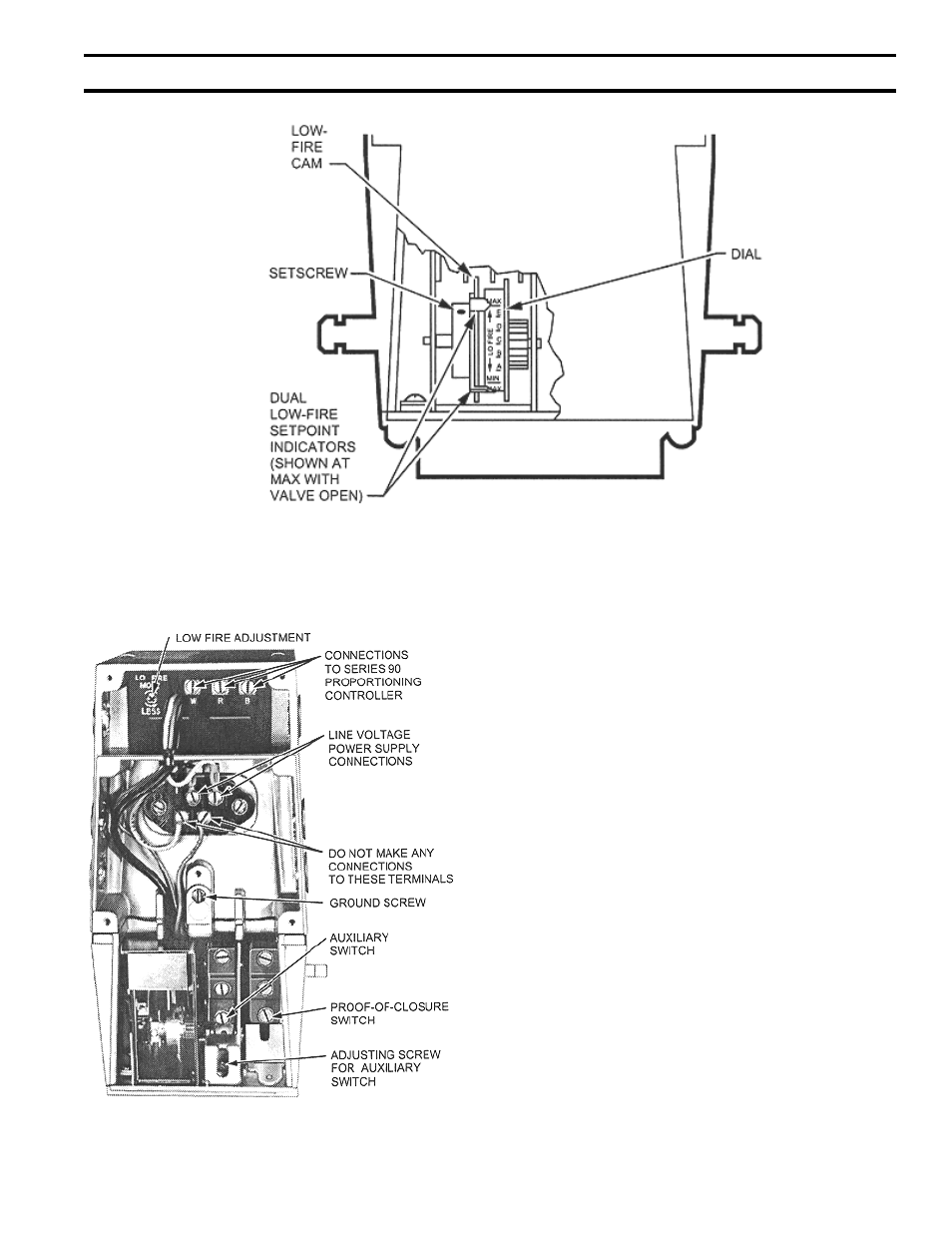
FIG. 53
LOW FIRE ADJUSTMENT - V4062 ACTUATOR
(3) Remove the lead to V9055A terminal R.
Jumper terminal R to W. This will prevent the
actuator from going to the high fire position.
(4) Energize the system and light the main burner.
(5) Use a Phillips screwdriver, or standard type with
a blade no more than 3/16 inch wide, to turn
the low fire adjusting screw for the desired low
fire position. DO NOT PUSH INWARD ON
SCREW.
(6) Shut down the burner, and then restart. Repeat
several times to be sure the low fire setting is
that desired and suitable for correct burner light
off.
(7) Turn off power supply. Remove R-W jumper,
and reconnect the lead to terminal R on the
V9055A.
(8) Replace the wiring compartment cover.
FIG. 54
LOW FIRE ADJUSTMENT - V9055A ACTUATOR
16.
MAIN BURNER FLAMES should have a clearly
defined inner cone, see Fig. 59 with no yellow tipping.
Orange-yellow streak caused by dust should not be
confused with true yellow tipping.
17
. CHECK PILOT FLAME. Flame should be a blue
medium hard flame enveloping approximately 3/8” of
the end of the thermocouple, flame sensor, or sensing
probe, see Fig. 60 thru 63.
SecTiON iV - OPeRATiON (continued)