Burnham Series 5B User Manual
Page 39
39
Venting
1.
INSTALL VENT CONNECTOR from canopy Draft
Hood or damper to chimney maintaining 6” clearances
from combustible materials.
2.
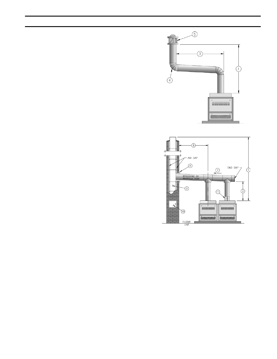
INSTALL VENT SYSTEM – Typical vent systems are
shown in Fig. 40 and 41. Some of the factors affecting
vent sizing and construction accompany these figures.
Vent installation shall be in accordance with local
building codes; or the local authority having
jurisdiction; or the National Fuel Gas Code, ANSI
Z223.1/NFPA 54; or the Standard for Chimneys,
Fireplaces, Vents and Solid Fuel Burning Appliances,
ANSI/NFPA 211. Both of the aforementioned
standards, ANSI Z223.1 and ANSI/NFPA 211,
specify Type B and Type L double wall metal vents
and fire clay tile lined masonry chimneys as suitable
chimney constructions for Category I, draft hood
equipped appliances, such as this Series 5B boiler.
Both standards prohibit the use of unlined masonry
construction as a chimney, with the exception in
ANSI Z223.1/NFPA 54 that “Where permitted by
the authority having jurisdiction, existing chimneys
shall be permitted to have their use continued when
an appliance is replaced by an appliance of similar
type, input rating and efficiency.” ANSI/NFPA 211
prohibits the use of single wall metal vent as a chimney,
while ANSI Z223.1 allows it under very restrictive
conditions.
In Canada, refer to CAN/CSA-B149.1 or .2-M86 and
local codes for venting.
SOME ITEMS RELATIVE TO CONSTRUCTION
AND SIZING OF VENT SYSTEM
(1) Total Vent Height.
(2) Vent Connector – make Initial Rise as high as
possible.
(3) Length of Lateral – hold to a minimum.
(4) Number of Elbows – hold to a minimum.
(5) UL Listed Vent Cap – assures full vent capacity
and freedom from adverse wind effects.
(6) Locate Boiler as close to Chimney as possible
consistent with necessary clearances, see page 7,
lower table.
(7) Run Breaching Horizontal and slope upward to
Chimney maximum of ¼” per ft.
(8) Use thimble where Breaching enters masonry
chimney – keep breaching flush with inside of flue
liner – do not connect into same leg of chimney
serving an open fireplace.
(9) Install vent above bottom of Chimney to prevent
blockage – inspect chimney for obstructions
or restrictions and remove – clean chimney if
necessary.
FIG. 40
SINGLE VENT SYSTEM
FIG. 41
MANIFOLD VENT SYSTEM
(10) Provide cleanout in chimney.
(11) Slip joint or draw band – facilitates installation and
future servicing when necessary.
(12) Venting of other appliances into same chimney
or into a common vent will affect sizing of the
chimney or common vent.
(13) Correction for altitude – design vent system for sea
level input.
(14) Provide adequate ventilation of Boiler Room, see
page 7 – this cannot be overemphasized.
(15) Never pass any portion of a vent system thru a
circulating air duct or plenum.
(16) Support of lateral runs so that vent pipe does not
sag.
(17) Support of common vent where it passes thru a
ceiling or roof.
SecTiON iii – iNSTALLATiON iNSTRUcTiONS (continued)