Burnham Series 5B User Manual
Page 20
20
FIG. 19
INSTALLATION OF JACKET END PANELS
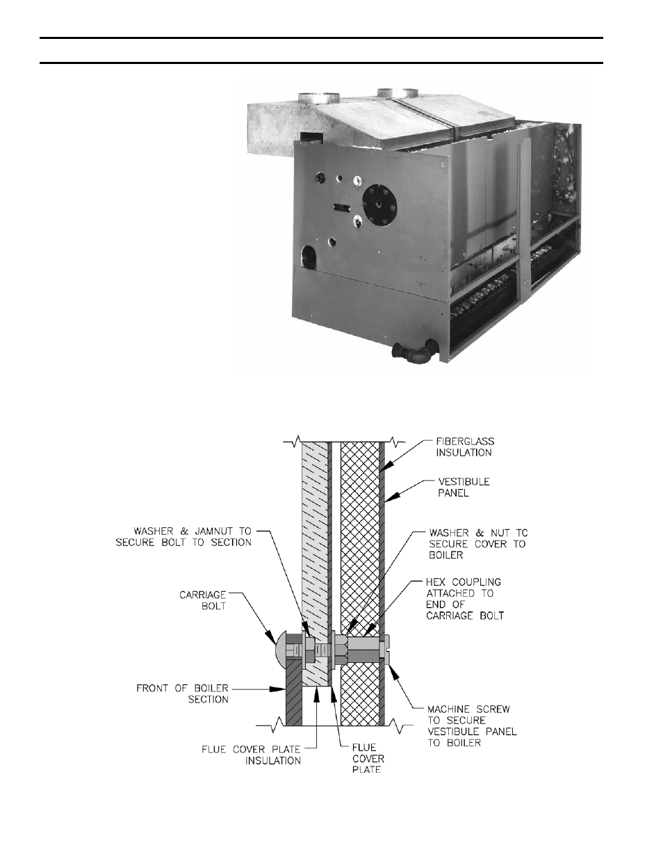
FIG. 20
VESTIBULE ATTACHMENT DIAGRAM
Attach Hex Couplings to end of
Carriage Bolts which secure flue
cover plates.
NOTE: Select Carriage Bolts which
line up with holes in the Vestibule
Panel.
18.
SECURE VESTIBULE PANEL TO
HEX COUPLINGS using ¼”-20 x
3/8” slotted pan head machine screws.
19
. ATTACH REAR TOP JACKET
PANEL TO UPPER END PANELS
using #8 SMS. Refer to Fig. 21.
20
. INSTALLATION OF CANOPY-
DRAFT HOOD 5006B thru 5010B
Section Boilers, see Fig. 22. Place
Cerafelt strips on top of section
assembly next to ledges formed by
center sections and next to ledge on
end sections. Overlap at corners.
21.
SECURE CANOPY-DRAFT HOOD
with 5/16”-18 x 5/8” MS driven into
the tapped lugs provided for this
purpose on top of the sections. Two
screws are required at each end.
Refer to Fig. 23.
SecTiON iii – iNSTALLATiON iNSTRUcTiONS (continued)
- 81433101R16-1/10 (40 pages)
- Gas-Fired (4 pages)
- Independence IN8 (1 page)
- Independence IN9 (92 pages)
- ALP105 (100 pages)
- 53A (22 pages)
- CHG150 (72 pages)
- Series 2B (52 pages)
- LEDV-3 (1 page)
- ALP399 (3 pages)
- MST513 (4 pages)
- HF SERIES (28 pages)
- SL AL119SL (1 page)
- PVG (64 pages)
- Independence PV (6 pages)
- V9A (64 pages)
- SERIES 3 1099-01R1-/10 (8 pages)
- RSA (52 pages)
- E4 (8 pages)
- SCG 1100-H4 (96 pages)
- SERIES 2 (6 pages)
- MEGASTEAM MST396 (68 pages)
- V7 SERIES (47 pages)
- V9 (4 pages)
- LE L7248 (28 pages)
- LEDV SERIES (36 pages)
- MST396 (64 pages)
- ES2 (52 pages)
- ALP080 (7 pages)
- Minuteman II (6 pages)
- PVG & SCG (4 pages)
- V8 Series (100 pages)
- FCM120 (80 pages)
- Carefree DOE (3 pages)
- 20_PV_I (32 pages)
- BOILERS (48 pages)
- MPO Series (4 pages)
- V8H Series (2 pages)
- 8H (92 pages)
- SM-6 (28 pages)
- SCG (92 pages)
- CHG (4 pages)
- ALPINE (8 pages)
- MULTI-PASS (108 pages)
- C4 SERIES (2 pages)