Burnham Series 5B User Manual
Page 33
33
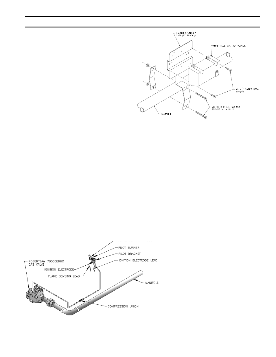
FIG. 31
INSTALLATION OF S8610M MODULE
EI Control System
1.
INSTALLATION OF GAS VALVE TRANSFORMER
AND PILOT PIPING (for Robertshaw Pilot Piping,
see Fig. 32) – Attach the bracket for mounting of the
junction box to the lower front corner of the Jacket
Upper End Panel using two #10-32 x ½” MS and nuts.
Mount junction box to bracket using #8 SMS, see Fig.
27 or 29. Connect pilot solenoid valve to bottom center
knockout of J-box using conduit fittings furnished,
(V88 Gas Train only) see Fig. 33. Mount transformer
on J-box. If Foot Mounted Transformer, connect to
J-box with Straight Connector, BX, Straight Connector
and ½” pipe coupling. Drill holes in Jacket and fasten
Transformer using SMS. Install RV-12LT pilot line
regulator (packed in Gas Train Carton) and other 1/8”
pipe fittings as shown in Section VI, Repair Parts (V88
Gas Train only).
Using ¼” OD aluminum tubing, connect the inlet of
the pilot solenoid valve to the pilot valve installed in
the manual shut off valve in the Gas Train. Using ¼”
aluminum tubing, complete installation to Pilot Burner,
see Fig. 33 (V88 Gas Train only).
2.
INSTALLATION OF BLEED PIPING (V88 Gas Train
only) – Using ¼” OD aluminum tubing, install a bleed
line on both diaphragm gas valves, connect together,
and, on USA boilers, run tubing to bleed line protruding
from inside base, see Fig. 33. On boilers installed in
Canada, run bleed line to outdoors.
FIG. 32
PILOT PIPING - EI CONTROL SYSTEM (Robertshaw7000)
U.S.A. 5006B THRU 5009B
SecTiON iii – iNSTALLATiON iNSTRUcTiONS (continued)
WITH GAS SUPPLY “OFF” and Service Piping
connected to the boiler, open Manual Valve(s) and
pilot valve(s) at end of Gas Train(s) and reduce
pressure to ½ lb. gage pressure. Using soap solution
or other approved method check gas train piping,
pilot piping, bleed piping and orifices for leaks.
3.
INSTALLATION AND WIRING OF S8610M
IGNITION CONTROL MODULE – Using two #10-32
x 2” MS, and nuts, install the S8610M module bracket
on the manifold just to the right of the main burner
with pilot, see Fig. 31. Using two #6 x ¾” SMS, install
the S8610M module on the bracket. Connect the two
wires from the Q3481B pilot to the S8610M module as
shown on Fig. 42, 43 or 44.
a. Ground Wire (200ºC) to “BNR GND” terminal
b. Ignition Sensor Wire to “Spark” terminal
Secure these wires to Pilot Piping with Wire Tie to
provide strain relief.
Using wiring harness furnished, connect leads with
push-on terminals on S8610M module as shown in
Fig. 42, 43 or 44. Run harness outside of jacket on
underside of manifold and secure in this position
with Wire Ties furnished. Connect the six wires in
the harness to the specified controls as shown in Fig.
42, 43 or 44.