Caution, Warning – Burnham Series 5B User Manual
Page 12
12
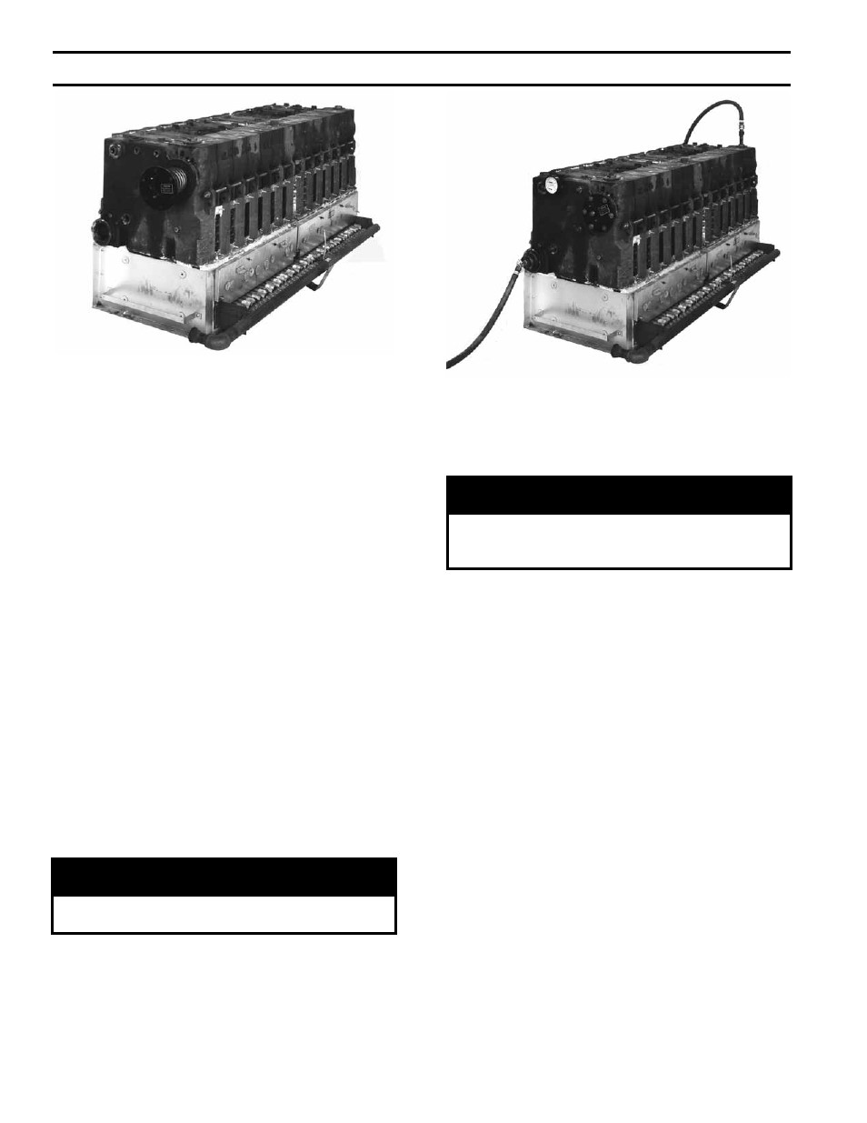
FIG. 8
INSTALLATION OF BUILT-IN HEATER
FIG. 9
TESTING BOILER ASSEMBLY FOR LEAKS
Open Steam or Water Trim Carton
8.
USE THE PLUGS IN THIS CARTON to plug tappings
in End Sections that will not be utilized on final
installation, see Fig. 7.
Open Tankless Heater Carton(s) If Supplied.
Open Heater Opening Cover Plate Carton(s).
9.
INSTALL BUILT-IN WATER HEATER(S) OR
HEATER OPENING COVER PLATE(S), See Fig.
8. Heater may be installed in either End Section or,
in some cases, in both End Sections. Heater Opening
Cover Plates are used to cover any unused heater
openings.
a. Place rubber gasket against surface of plate and
align holes.
b. Place washer on each of 3/8” Cap Screws furnished
and insert cap screws through plate and gasket.
Start all screws in taps before final tightening.
10.
HYDROSTATIC TEST, see Fig. 9: After the boiler
sections have been assembled, it is essential that the
boiler be hydrostatically tested before the canopy, flue
cover plates, jacket, or piping is installed.
a. Plug all boiler tappings and fill boiler completely
with cold water.
cAUTiON
DO NOT install gauge until after hydrostatic
testing the boiler. Gauge failure may result.
b. All completed boilers must satisfactorily pass the
prescribed hydrostatic test.
(1) STEAM BOILERS: The assembled boiler must
be subjected to a hydrostatic test of 45 psig to 55
psig.
(2) HOT WATER BOILERS: The assembled boiler
must be subjected to a hydrostatic test of 75 psig
to 85 psig.
WARNiNG
Failure to properly hydrotest all boilers at the
correct pressure may result in section assembly
failure in operation.
11.
EXAMINE BOILER CAREFULLY, INSIDE AND
OUTSIDE, to insure against leaks from cocked nipples
or through concealed breakage caused in shipping and
handling. This precaution is for your protection and
will simplify handling of necessary replacements and
adjustment claims. After making certain that there are
no leaks, drain boiler and remove plugs for boiler trim
and other connections.
Open Boiler Sealing Carton.
12.
SEAL BETWEEN BOILER SECTIONS AND BASE,
see Fig. 10.
a. Push ¾” braided ceramic fibre Rope (furnished) into
gap between bottom of End Section and Low Base
End Panel until rope touches Front and Rear Base
Frames. Place the 1-1/2” x 2” x 5/8” steel spacers
between low base panel and section and in front of
rope – align holes. Secure section to low base end
panel with 3/8”-16 x 2” Cap Screws, washers and
nuts.
b. Secure opposite end section to high base end panel
with 3/8”-16 x 2” Cap Screws, washers and nuts.
c. Apply Furnace Cement to gaps between section
assembly and base to make gas tight seal.
d. Check all joints between Boiler sections and use
remaining Furnace Cement or Sealer Compound to
make joints gas tight.
SecTiON iii – iNSTALLATiON iNSTRUcTiONS (continued)