Caution – Burnham Series 5B User Manual
Page 62
62
cAUTiON
The following procedures should only be
performed by a qualified service technician.
15.
MINIMUM INPUT ADJUSTMENTS
This section covers Minimum Input Adjustments on
Honeywell V8944B Diaphragm Type “Lo-Hi-Lo” Gas
Valves, Honeywell V5055B Fluid Power Gas Valves
equipped with either a V4062A “Lo-Hi-Lo” Actuator or
a V9055A “Modulating” Actuator.
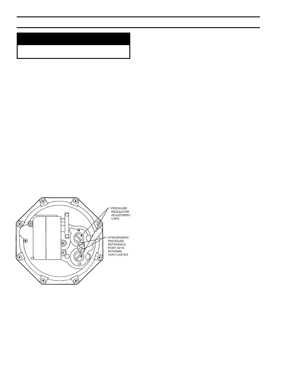
a. Minimum Input Adjustments – “Lo-Hi-Lo”
Combination Valve, V8944B (Natural Gas Only)
On boilers equipped with the V8944B combination
diaphragm valve/regulator, Low Fire Adjustment
should not be less than Minimum Input shown on
Rating Plate (1/3 of full rated input). Fig. 52 shows
the outlet pressure adjustment screws for low and
high fire. The V8944B low and high fire pressure
settings are factory set at 0.8” and 3.5” W.C.
respectively. If further adjustments are necessary,
remove pressure regulator adjustment caps and
insert a screwdriver to raise or lower the regulator
pressure.
c. MINIMUM INPUT ADJUSTMENTS –
MOTORIZED “MODULATING” ACTUATOR,
V9055A
On boilers equipped with Fluid Power Valves that
have “Modulating” Actuators, Low Fire Adjustment
should not be less than Minimum Input shown on
Rating Plate (1/3 of full rated input).
Fig. 54 shows the Low Fire Adjusting Screw for
increasing or decreasing low fire input on the
Honeywell V9055A “Modulating” Actuator. To
adjust the low fire setting after the burners are “on”,
the following procedure should be used.
(1) With power to actuator “off”, remove the wiring
compartment cover.
(2) Check to make sure the low fire adjustment is
set at MAX (full clockwise) to insure a safe
light-off. (Low fire adjustment is preset at the
factory in the MAX position.)
Fig. 53 shows the Limit Switch Cam and Scales to
indicate direction to rotate cam for increasing or
decreasing low fire input on the Honeywell V4062A
“Lo-Hi-Lo” Actuator. To adjust the low fire setting
after the burners are “on”, the following procedure
should be used.
(1) With power to actuator “off”, remove the
wiring compartment cover.
(2) Check to be sure the low fire adjustment is set
at MAX to insure a safe light-off. (Low fire
adjustment is preset at factory in the MAX
position.)
(3) Disconnect the controller lead from terminal #4
on the actuator to keep the valve in the low fire
position.
(4) Start the system and establish the main burner
flame.
(5) Loosen the setscrew in the cam (Fig. 53) with
the special wrench taped to inside of actuator
cover. Keep the wrench seated in the setscrew.
Rotate the cam slightly downward (by moving
the wrench toward the base of actuator) to open
bleed valve. Actuator will start to close.
(6) When valve reaches desired low fire position,
quickly tighten setscrew and remove wrench. If
the desire low fire setting is “missed”, merely
loosen the setscrew and rotate cam in the
opposite direction to the desired set point.
(7) Shut down burner, and then restart. Repeat
several times to be sure the low fire setting
is that desired and suitable for correct burner
lightoff. Readjust if necessary.
(8) Disconnect power and reconnect controller lead
removed in step (3) above.
(9) Replace the wiring compartment cover.
b. MINIMUM INPUT ADJUSTMENTS –
“Lo-Hi-Lo” MOTORIZED ACTUATOR, V4062A
On boilers equipped with Fluid Power Valves that
have “Lo-Hi-Lo” Actuator, Low Fire Adjustment
should not be less than Minimum Input shown on
Rating Plate (1/3 of full rated input).
SecTiON iV - OPeRATiON (continued)
FIG. 52
V8944B COMBINATION VALVE