Burnham Series 5B User Manual
Page 36
36
Run these wires to outside of jacket on underside of
manifold and secure in this position with Wire Ties
furnished to provide strain relief. Provide adequate
support and strain relief for wiring outside jacket.
4.
COMPLETION OF WIRING – Connect power supply
fused disconnect switch, service switch, primary and
secondary side of gas valve transformer, primary side of
ignition transformer, and remaining controls – see Fig.
46 – 49 for wire type and connections to be made. All
wiring must be adequately supported and strain relief
provided. All wiring including ground connections
must comply with the requirements of the authority
having jurisdiction and, in the absence of such, to the
National Electrical Code, ANSI NFPA No. 70-2005,
or the Canadian Electrical Code, C22.1, whichever is
applicable.
EP Control System
1.
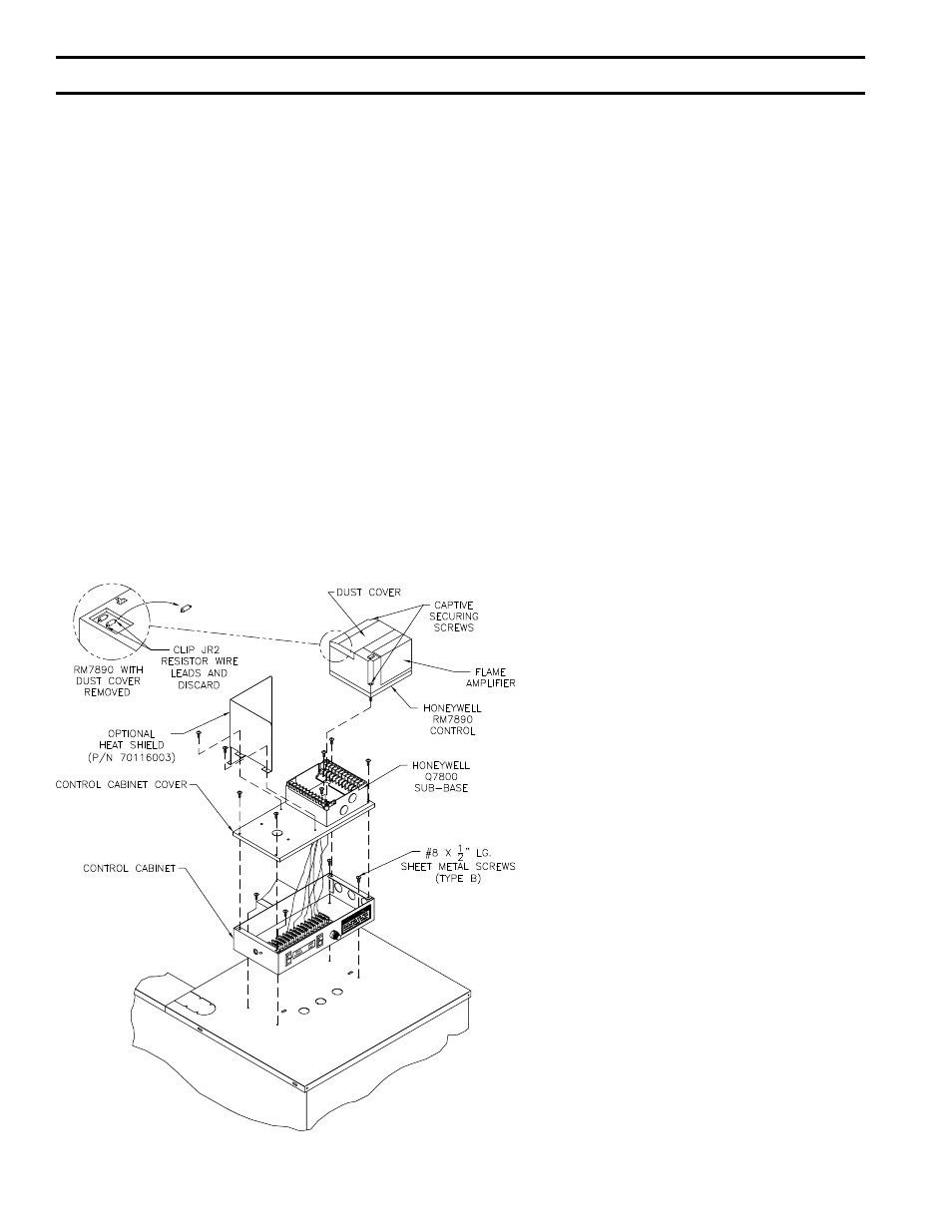
INSTALLATION OF “EP PANEL”, - Attach the EP
Control Panel with RM7890 control, see Fig. 36, to
the front top jacket panel, preferably on the closest
jacket panel to the gas train installed. There are (3)
three KO’s and (4) four fastening holes provided for
this purpose, use (4) four #8 SMS to fasten the Control
FIG. 36
INSTALLATION OF OP AND EP
CONTROL PANEL
Panel to the front top jacket panel. If Foot
Mounted Transformer, connect to J-box using
straight connector, BX, straight connector and
½” pipe nipple. Drill holes in Jacket and fasten
Transformer using SMS.
2.
INSTALLATION OF PILOT PIPING – Install
the H91WA-4 pilot solenoid valve in the bottom
center knockout of the J-box using conduit fittings
furnished, see Fig. 37. Install RV-12LT regulator,
(Packed in Gas Train Carton) and 1/8” tee in the
¼” OD pilot tubing as shown in Fig. 37.
3.
INSTALLATION OF BLEED PIPING – Using
¼” OD aluminum tubing, install a bleed line on
both diaphragm valves, connect together, see Fig.
27 or 29, and, on USA boilers, run tubing to bleed
line protruding from inside base, see Fig. 37.
On boilers installed in Canada, run bleed line to
outdoors.
4.
INSTALLATION OF IGNITION
TRANSFORMER AND WIRING OF PILOT – If
space permits, mount the ignition transformer on
the Jacket above the Gas Train using four #8 x
½” SMS. Holes will have to be drilled for this
purpose. If space does not permit mounting the
Ignition Transformer on the Jacket, install the
Ignition Transformer on a nearby wall.
Connect the two wires from the Q179C pilot to
the RM7890 sub-base as follows:
a. Ground Wire (200ºC) to the “12” terminal
b. Flame detector wire (Honeywell 1298020) to
“11” terminal
c. Ignition Cable (Honeywell 1061012) to the
Secondary (High Voltage) terminal of the
Ignition Transformer
Run these wires to outside of jacket on underside
of manifold and secure in this position with Wire
Ties furnished to provide strain relief. Provide
adequate support and strain relief for wiring
outside jacket.
SecTiON iii – iNSTALLATiON iNSTRUcTiONS (continued)