Connecting your tv and dvd player, Connecting your equipment 03 – Pioneer SC-LX90 User Manual
Page 20
Connecting your equipment
03
20
En
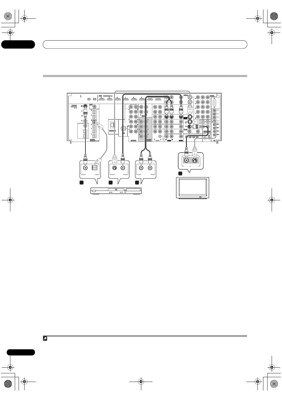
Connecting your TV and DVD player
The diagram shows a basic setup of this amplifier
together with a TV and DVD player, with S-Video or
composite video connections. Different TVs and DVD
players may offer alternative connections. See also
Using
the component video jacks on page 24 if your TV and/or
DVD player has component video inputs/outputs. If your
DVD player offers multichannel analog audio outputs,
see
Connecting the multichannel analog inputs on
page 60.
1
Connect the MONITOR OUT video jack to a video
input on your TV.
Use a standard RCA/phono jack video cable to connect to
the composite video jack, or for higher quality video, use
an S-Video cable to connect to the S-Video jack.
2
Connect a composite or S-Video output on your
DVD player to the DVD/LD VIDEO or DVD/LD S-VIDEO
input.
Connect using a standard video cable or an S-Video
cable.
3
Connect a coaxial-type
1
digital audio output on
your DVD player to the COAXIAL IN 1 (DVD/LD) input.
Use a coaxial cable designed for digital audio.
4
Connect the stereo audio outputs on your DVD
player to the DVD/LD AUDIO inputs.
Connect using a stereo RCA/phono jack cable.
• If your DVD player has multichannel analog outputs,
you can connect these instead. See also
Connecting
the multichannel analog inputs on page 60.
5
If the source component is an LD player with a 2
RF digital audio output, connect this to the RF IN input
on this amplifier.
To ensure compatibility with all laserdiscs, connect both
the
PCM and 2 RF outputs from your LD player.
• Use a coaxial cable designed for digital audio for the
2 RF connection.
• You may need to assign the
RF IN digital input when
setting up the amplifier (see also
The Input Setup
menu on page 94).
S400
S400
(AUDIO)
(For LD)
ASSIGNABLE
6
1
ASSIGNABLE
L
R
VIDEO
AUDIO
L
R
AUDIO
L
L
L
R
R
L
R
R
L
L
R
R
L
R
L
R
AUDIO
ZONE3
OUT
ZONE2
OUT
ZONE2
OUT
ZONE3
OUT
MONITOR
OUT
OUT
IN
1
IN
2
IN
3
IN
4
1
OUT
2
OUT
3
OUT
4
IR
CONTROL
COMPONENT
VIDEO
ASSIGN-
ABLE
ASSIGN-
ABLE
VIDEO
IN
OUT
SUB
WOOFER
FRONT
CENTER
1
2
1
2
EXTRA
SUR-
ROUND
(Single)
SUB W.
FRONT
CENTER
SUR-
ROUND
SUR-
ROUND
BACK
SURROUND
BACK
PRE OUT
MULTI CH
IN
IN
1
IN
2
IN
3
IN
4
IN
5
IN
6
OUT1
(HDMI CTRL)
OUT2
HDMI
RF IN
IN
(TV)
1
IN
(SAT)
2
IN
(DVR/
VCR 1)
3
IN
(DVR/
VCR 2)
4
IN
(VIDEO/
GAME
1)
5
IN
(CD-R/
TAPE/
MD)
6
(DVD/LD)
2
IN
1
(BD)
IN
2
(CD)
IN
3
(SACD)
IN
4
COAXIAL
1
4
ASSIGNABLE
OPTICAL
1
6
ZONE2
OUT
SOURCE
OUT
ZONE3
/SOURCE
OUT
1
2
3
4
12 V TRIGGER
(DC OUT 12V TOTAL 250 mA MAX)
RS-
232C
VIDEO/
GAME 1
IN
SAT
IN
IN
IN
TUNER
IN
IN
IN
CD-R/
TAPE/
MD
REC
SEL
OUT
CD
SACD
PHONO
TV
IN
BD
IN
DVD/LD
IN
IN
IN
IN
(DVD/LD)
IN
(DVD/LD)
1
1
5
IN
(VIDEO/
GAME
1)
3
IN
(BD)
2
IN
(DVR/VCR 1)
4
IN
(DVR/VCR 2)
5
IN
ZONE2
OUT
DVR/
VCR 2
DVR/
VCR 1
REC SEL
OUT
REC SEL
OUT
IN
REC SEL
OUT
REC SEL
OUT
S-VIDEO
Y
P
B
P
R
LAN (10/100)
IN
iPod
DVD/LD
IN
ASSIGN-
ABLE
IN
(DVD/LD)
MONITOR
OUT
(DVD/LD)
IN
1
IN
(DVR/
VCR 1)
3
L
R
VIDEO
AUDIO
VIDEO
IN
S-VIDEO
IN
S-VIDEO
OPTICAL
DIGITAL OUT
VIDEO OUT
COAXIAL
AUDIO
R
L
ANALOG OUT
1
3
2
4
SC-LX90
DVD player
TV
Note
1 If your DVD player only has an optical digital output, you can connect it to one of the optical inputs on this amplifier using an optical cable. When you set
up the amplifier you’ll need to tell the amplifier which input you connected the player to (see
The Input Setup menu on page 94).
SC_LX90_WY.book Page 20 Wednesday, February 6, 2008 11:49 AM