4 the switcher port rc command area, 5 the keypad lcd port rc command area, 6 the button color port rc command area – Kramer Electronics SV-551 User Manual
Page 29: Figure 24: switcher port rc command area, Figure 25: switcher port rc command area, Figure 26: button color port rc command area
The RC Configuration Software
25
4.5.3.4
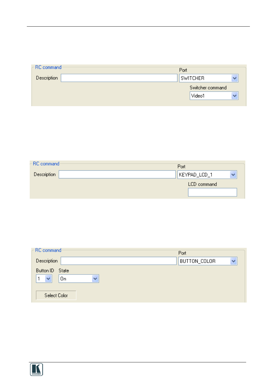
The Switcher Port RC Command Area
The switcher port command area includes the SV-551 Switcher command
drop-down box:
Figure 24: Switcher Port RC Command Area
4.5.3.5
The Keypad LCD Port RC Command Area
The keypad LCD port RC Command area includes the LCD command drop-
down box, which lets you type any text (up to 8 characters) to the LCD
display on the control device:
Figure 25: Switcher Port RC Command Area
4.5.3.6
The Button Color Port RC Command Area
The button color port RC Command area lets you select the button color and
state (On Off, Fast Blink and Slow Blink) for each button:
Figure 26: Button Color Port RC Command Area