5 the kramer rc-sv configuration main window, The kramer rc-sv configuration main window, Figure 17: the kramer rc configuration main window – Kramer Electronics SV-551 User Manual
Page 24: Table 5: kramer rc configuration window features, Table 5 , and defines it, The rc configuration software
KRAMER: SIMPLE CREATIVE TECHNOLOGY
The RC Configuration Software
20
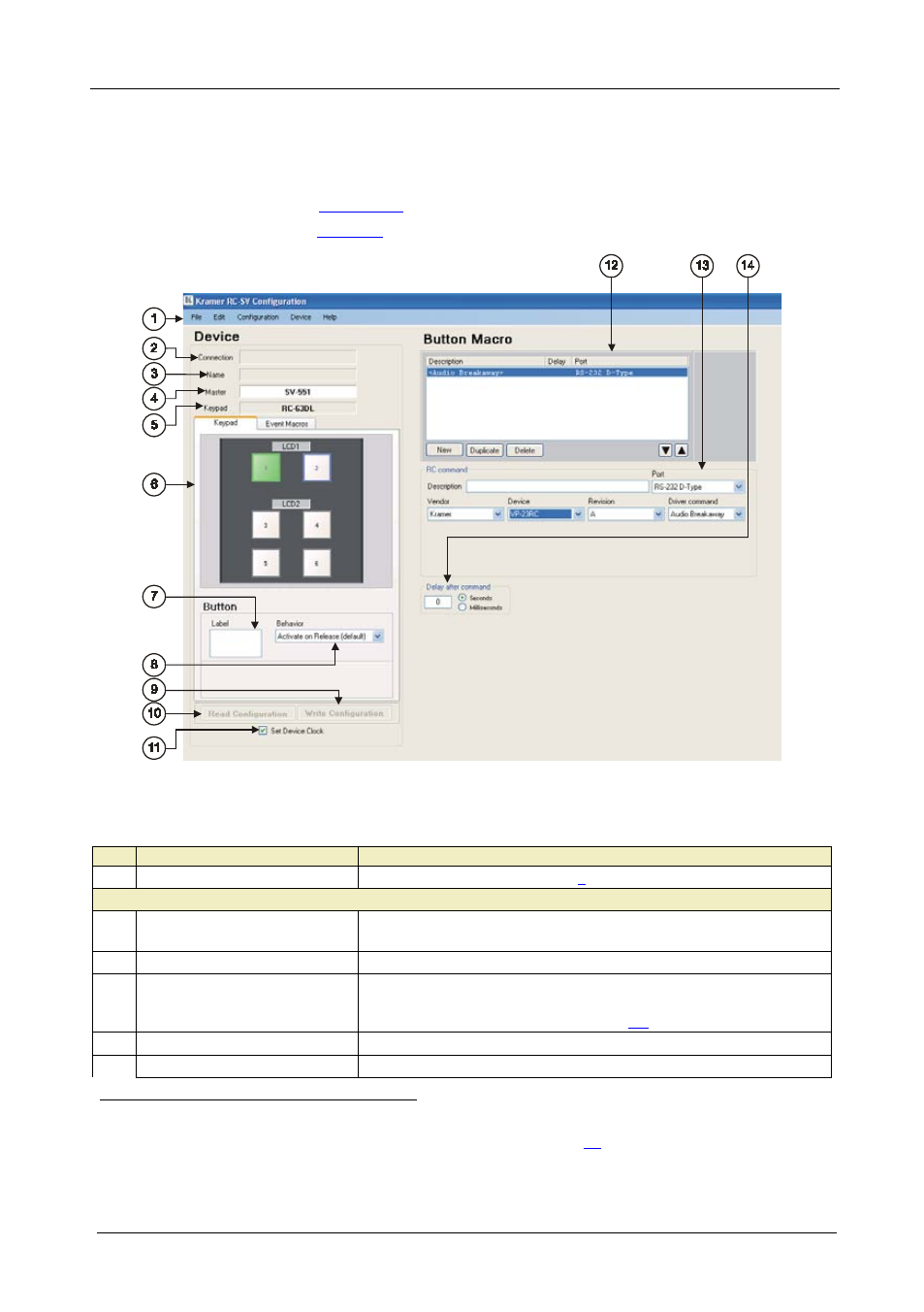
4.5 The Kramer RC-SV Configuration Main Window
After importing the drivers and defining the ports, use the Kramer RC
Configuration main window to assign a sequence of commands (the macro)
for each RC button.
illustrates the Kramer RC-SV Configuration
main window
Figure 17: The Kramer RC Configuration Main Window
Table 5: Kramer RC Configuration Window Features
#
Feature
Function
1
Menu Bar
Menus are described in section
Device Area
2
Connection Box
Displays the connection properties with the device (IP address or
com port)
3
Name Box
Displays the name of the specific device
4
Master Box
Displays the Master device to which the auxiliary device keypad is
connected. Change the master device type and the auxiliary device
Keypad via the File menu (see section
5
Keypad Box
Select the device type
6
Keypad Tab
Shows the layout of the RC buttons according to the device type
1 The Window appearance is slightly different for each machine (for example, the keypad is specific to the machine selected)
2 The name and IP number are initially set by the Properties dialog box (see section
3 The device type can be selected only if there is no device connected to the computer. If a device is connected, the device
type is selected automatically