2 the light rc command area, 3 the relay port rc command area, Figure 22: light rc command area – Kramer Electronics SV-551 User Manual
Page 28: Figure 23: relay port rc command area, Table 6
KRAMER: SIMPLE CREATIVE TECHNOLOGY
The RC Configuration Software
24
Table 6: IR, RS-232 and RS-485 Port Command Area Features
Drop-down Box
Description
Vendor Drop-down Box
Displays the current vendor. Select the vendor when writing a
new RC command or modifying a selected command
Device Drop-down Box
Displays the device driver name. Select the device driver when
modifying or writing a new RC command
Revision Drop-down Box
Displays the device driver revision. Select a revision when
modifying or writing a new RC command
Driver command Drop-down Box
Displays the current driver command. Select a driver command
when writing a new command or modifying a selected command
4.5.3.2
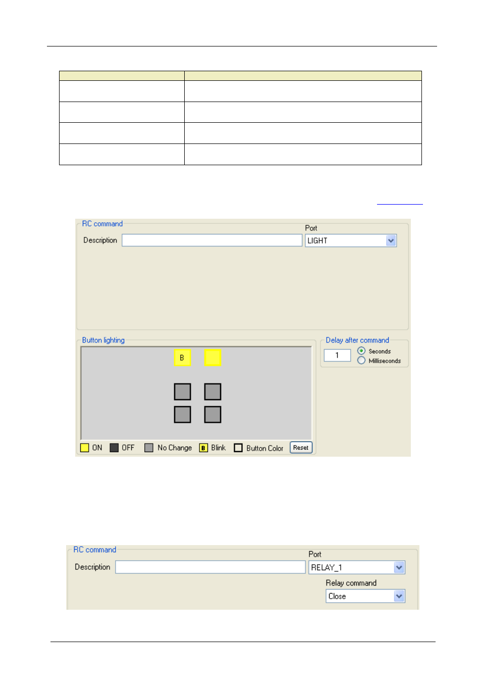
The LIGHT RC Command Area
The LIGHT Command lets you set the button lighting behavior (see
Figure 22: LIGHT RC Command Area
4.5.3.3
The Relay Port RC Command Area
The relay RC Command Area includes the Relay command drop-down box
(Close, Open):
Figure 23: Relay Port RC Command Area