Figure 13: ir command area window, Figure 14: ir emitter wiring, Figure 13 – Kramer Electronics SV-551 User Manual
Page 21
The RC Configuration Software
17
Figure 13: IR Command Area Window
You can test the IR command by connecting the RC unit IR terminal block
connectors to the device via the IR emitter, and then clicking the IR-Out
Testing button.
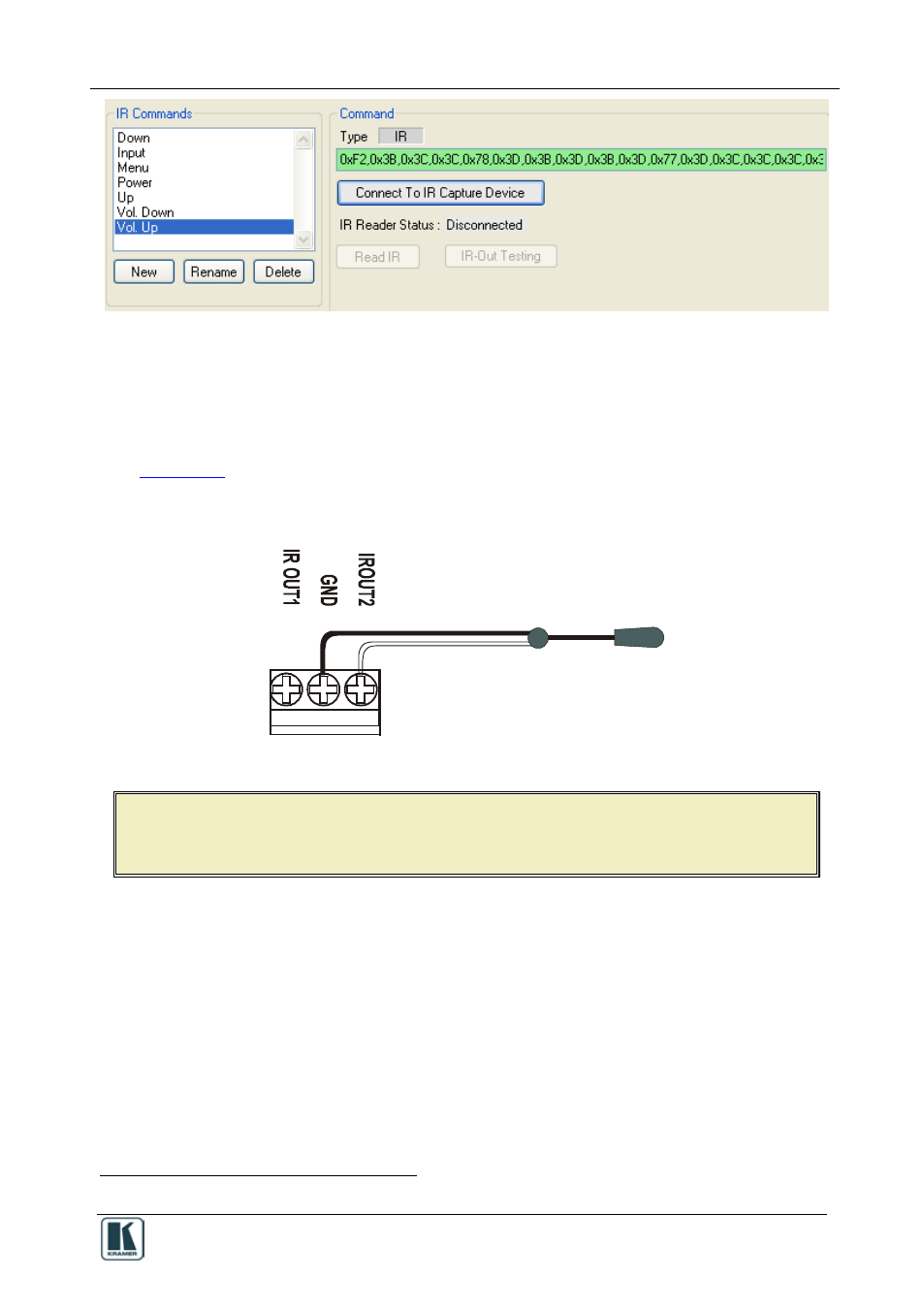
shows how to connect the IR emitter
. The white striped side
connects to IR OUT, the black side connects to the Ground, and the LED
Emitter Shell is affixed to the IR sensor window with the adhesive layer.
Figure 14: IR Emitter Wiring
NOTE: The dual IR emitter emits a weaker IR signal that may not be detected
by some devices
1 Using the Kramer 3.5mm to IR Emitter Control Cable (C-A35/IRE-10)