4 the switcher port rc command area, 5 the keypad lcd port rc command area, 6 the button color port rc command area – Kramer Electronics SV-551 User Manual
Page 29: Figure 24: switcher port rc command area, Figure 25: switcher port rc command area, Figure 26: button color port rc command area
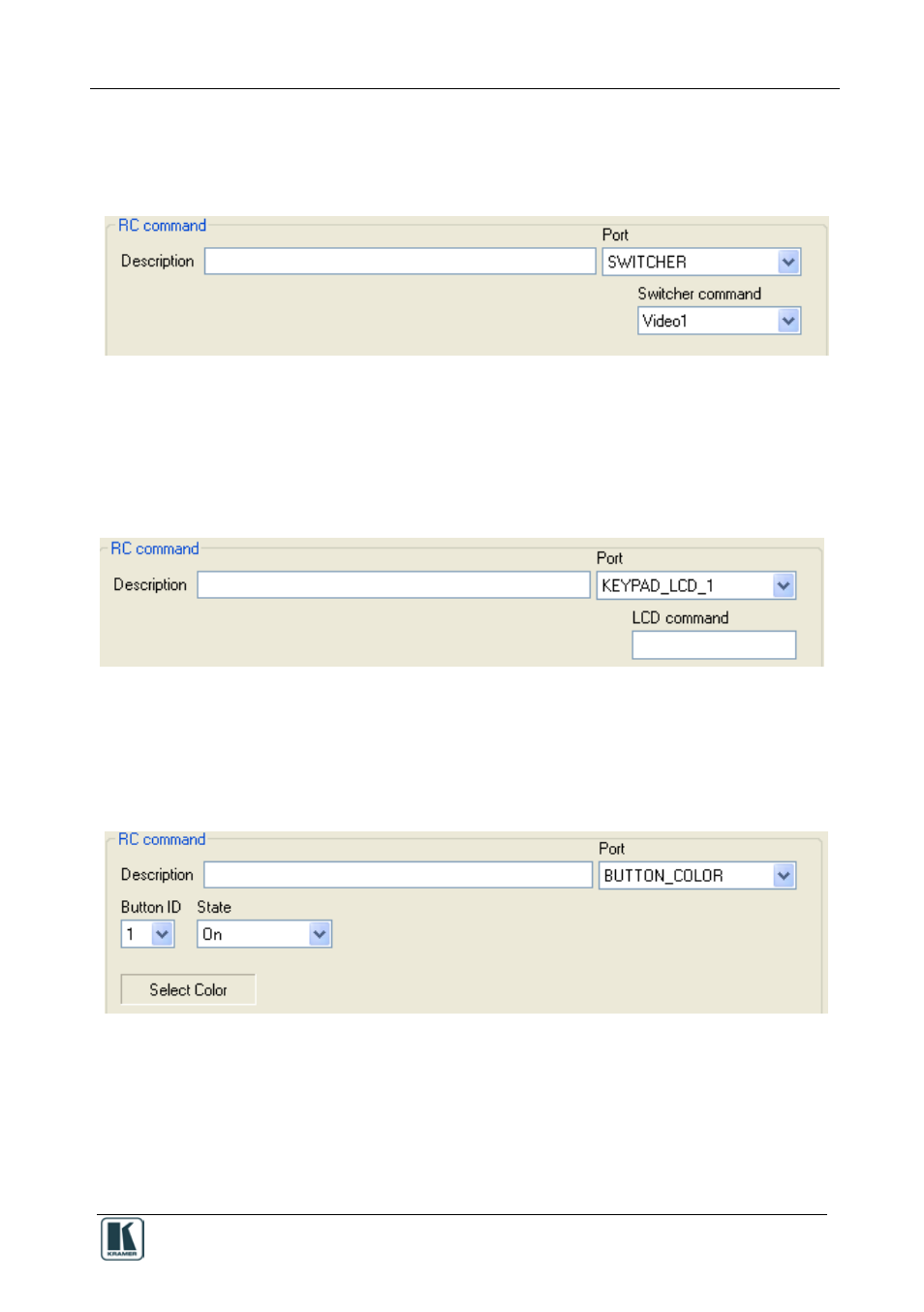 4 the switcher port rc command area, 5 the keypad lcd port rc command area, 6 the button color port rc command area | Figure 24: switcher port rc command area, Figure 25: switcher port rc command area, Figure 26: button color port rc command area | Kramer Electronics SV-551 User Manual | Page 29 / 51