Allied Telesis FastPrint Server User Manual
Page 13
Chapter 1. Introduction
Features
FastPrint Server User’s Guide
3
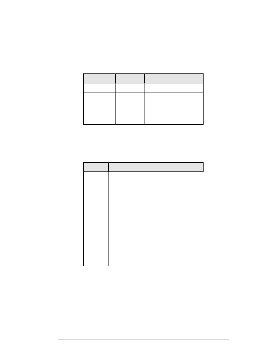
1.2.1. LED Indicators
There are two LED indicators on the top of the FastPrint Server. The red LED is the
Status/Error indicator. The green LED is the Power/Link indicator. See the previous
figures to locate the LEDs on your model. The LED indicator modes are described in the
following table.
Green LED
Green LED
Red LED
Red LED
Status Description
Status Description
Solid Off
Solid Off
No power.
Solid On
Solid On
Hardware error.
Solid On
Solid Off
Normal operation.
Flashing
Off
Transmitting or receiving
packets from the network.
Table 1: LED Indicators
1.2.2. 10/100BaseT Switches
The FastPrint has 2 DIP switches. See the previous diagrams to locate these switches.
Operation of these switches is described below.
Switch
Switch
Description
Description
1
Auto Negotiation Switch.
When ON (UP position), the FastPrint will
select 10BaseT/100BaseT and Full/Half
Duplex as required. The recommended
position is ON; switches 2 & 3 are disabled
when Auto Negotiation is ON.
2
10/100BaseT Manual Select Switch.
Set UP for 100BaseT or DOWN for 10BaseT.
Switch 1 must be OFF for this switch to
function.
3
Full/Half Duplex Switch.
Set UP for Full duplex operation or DOWN for
Half Duplex operation.
Switch 1 must be OFF for this switch to
function.
Table 2: DIP Switches