Burner maintenance – A.O. Smith 3400 User Manual
Page 75
75
5. Loosen the seven bolts on the blower adapter at the base
and move the burner ground wire (Green) aside.
6. Lift the blower adapter and remove the manifold assembly
up from the 6 studs located on the cover plate and remove
the burner gasket.
7. Remove any loose foreign material such as dust or lint with a
vacuum. Check all ports for blockage. Dislodge any foreign
material causing blockage. Remove any soot or carbon
deposits with a rag making sure to remove any lint left on
the burner by vacuuming again.
8. Reverse the steps to reassemble the unit.
9. Restore electrical power and gas supply to the boiler.
• Put the boiler back in operation by following the Lighting
and Operating instructions in this manual.
• Check for gas leaks and proper boiler and vent
operation.
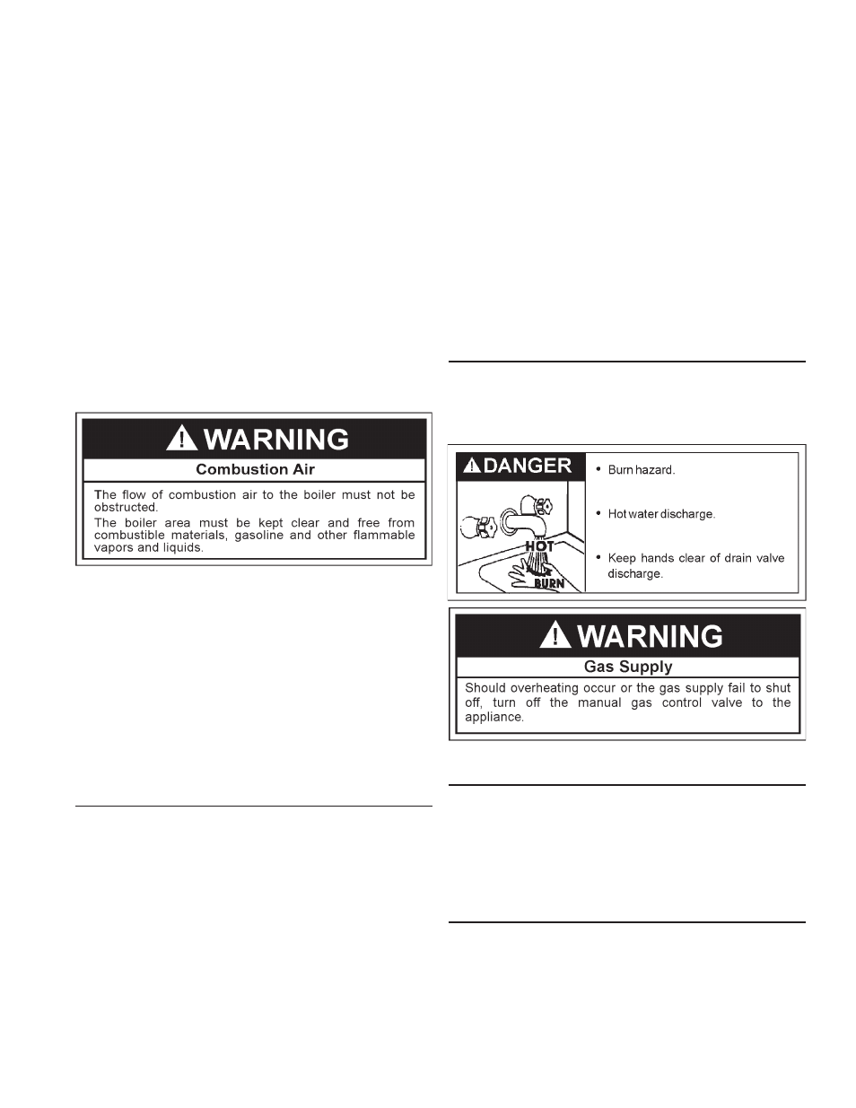
PRESSURE RELIEF VALVE
The pressure relief valve should be opened at least twice a year
to check its working condition. This will aid in assuring proper
pressure relief protection. Lift the lever at the top of the valve
several times until the valve seats properly and operates freely.
BLOWER COMPARTMENT
The blower compartment should be cleaned annually to remove
any dirt and lint that may have accumulated in the compartment
or on the blower and motor. Buildups of dirt and lint on the
blower and motor can create excessive loads on the motor
resulting in higher that normal operating temperatures and
possible shortened service life.
AIR FILTER BOX
The air filter box should be cleaned every three months to remove
any dust and debris that may have accumulated in the air filter
or the filter housing. Buildups of dust on the air filter can block
the air intake into the boiler. Air filter can washed and cleaned
with water.
If the preceding burner characteristics are not evident, check for
accumulation of lint or other foreign material that restricts or blocks
the air openings to the burner or boiler. To check burners:
1. Shut off all gas and electricity to unit. Allow unit to cool.
2. Remove main burners from unit.
3. Check that burner ports are free of foreign matter.
4. Clean burner with vacuum cleaner. Do not distort burner
ports.
5. Reinstall burners in unit. Ensure that all the screws on the
burner flange are tightened securely so that the gasket will
provide a good seal.
6. Also check for good flow of combustion and ventilating air
to the unit.
After placing the boiler in operation, check the ignition system
safety shut-off devices for proper operation. To accomplish this
with the main burner operating, close the valve on the manifold.
Within four seconds the main burners should extinguish. If this
does not occur immediately, discontinue gas supply by closing
main manual shut-off and call a qualified service technician to
correct the situation. If the burners extinguish, then light boiler in
accordance with lighting and operating instructions.
Any safety devices including low water cutoffs used in conjunction
with this boiler should receive periodic (every six months)
inspection to assure proper operation. A low water cutoff device
of the float type should be flushed every six months. Periodic
checks, at least twice a year, should be made for water leaks.
More frequent inspections may be necessary depending on
water conditions.
The boiler-mounted gas and electrical controls have been
designed to give both dependable service and long life.
However, malfunction can occur, as with any piece of equipment.
It is therefore recommended that all components be checked
periodically by a qualified service technician for proper operation.
BURNER MAINTENANCE
Qualified service technician should follow this procedure when
the boiler’s burner needs cleaning.
1. Turn off the electrical power to the boiler and close the main
manual gas shutoff valve(s). Allow the boiler parts to cool
before disassembly.
2. Loosen the flange and separate the gas train from the
manifold assembly.
3. Separate the burner from the blower adapter by first
removing the four (4) bolts and subsequently, the blower
gas kets. The blower should be free to move at this point.
4. For Direct Vent units: It is necessary to loosen and slide
the rubber coupling on the blower adaptor in order to
move the blower.